Diaphragm valves, valve components, and methods for forming valve components

a technology of diaphragm valve and valve body, which is applied in the direction of diaphragm valve, engine diaphragm, valve operating means/release devices, etc., can solve the problems of diagram valve leaking, precursor decomposition within the diaphragm, and even blocking the valve channel

Active Publication Date: 2020-01-16
ASM IP HLDG BV
View PDF5 Cites 234 Cited by
  • Summary
  • Abstract
  • Description
  • Claims
  • Application Information

AI Technical Summary

Benefits of technology

[0010]For the purpose of summarizing the invention and the advantages achieved over the prior art, certain objects and advantages of the invention have been described herein above. Of course, it is to be understood that not necessarily all such objects or advantages may be achieved in accordance with any particular embodiment of the invention. Thus, for example, those skilled in the art will recognize that the invention may be embodied or carried out in a manner that achieves or optimizes one advantage or group of advantages as taught or suggested herein without necessarily achieving other objects or advantages as may be taught or suggested herein.

Problems solved by technology

For example, if the wetted surfaces of the diaphragm valve exceed the operational temperature window for a particular precursor then the precursor may decompose within the diaphragm valve prior to entering the reaction chamber.
Conversely, if the wetted surfaces of the diaphragm valve are below the operational temperature window for a particular precursor, then the precursor may condense or even solidify in the valve channel causing the diagram valve to leak or even blocking the valve channel.

Method used


Image

  • Diaphragm valves, valve components, and methods for forming valve components
  • Diaphragm valves, valve components, and methods for forming valve components
  • Diaphragm valves, valve components, and methods for forming valve components

Examples


Embodiment Construction

[0021]Although certain embodiments and examples are disclosed below, it will be understood by those in the art that the invention extends beyond the specifically disclosed embodiments and / or uses of the invention and obvious modifications and equivalents thereof. Thus, it is intended that the scope of the invention disclosed should not be limited by the particular disclosed embodiments described below.

[0022]The illustrations presented herein are not meant to be actual views of any particular material, apparatus, structure, or device, but are merely idealized representations that are used to describe embodiments of the disclosure.

[0023]As used herein, the term “substrate” may refer to any underlying material or materials that may be used, or upon which, a device, a circuit or a film may be formed.

[0024]As used herein, the term “atomic layer deposition” (ALD) may refer to a vapor deposition process in which deposition cycles, preferably a plurality of consecutive deposition cycles, ar...


PUM


Abstract

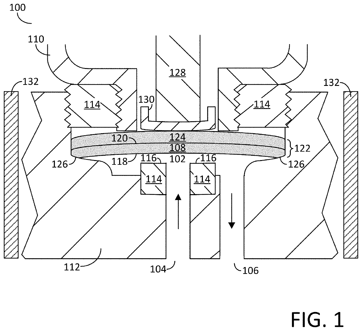
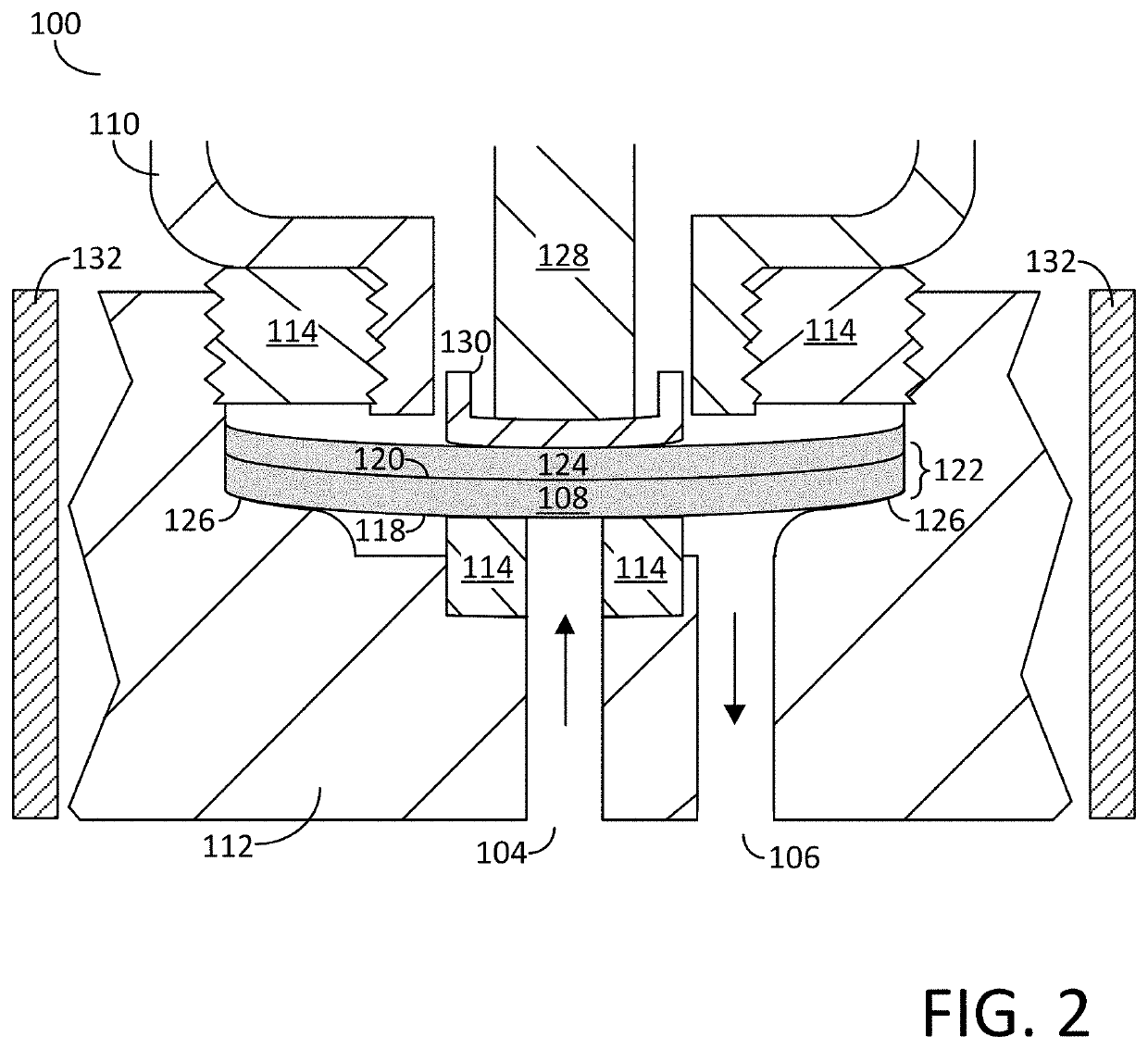
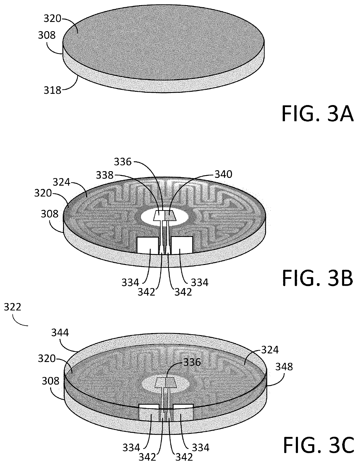
A diaphragm valve is disclosed. The diaphragm valve may include, a valve body comprising a valve channel, the valve channel including an inlet channel and an outlet channel. The diaphragm valve may also include, a valve seat adjacent to the valve channel and a flexible diaphragm comprising a wetted surface and an opposing non-wetted surface, the flexible diaphragm being disposed adjacent to the valve channel. The diaphragm valve may also include, a flexible heater disposed over the non-wetted surface of the flexible diaphragm, and a valve actuator that is operable to operable to move the wetted surface of the flexible diaphragm into and out of contact with the valve seat. Valve components including a flexible heater and methods for forming such valve components are also disclosed.

Description

FIELD OF INVENTION[0001]The present disclosure relates generally to a diaphragm valve and in particular, a diaphragm valve comprising a valve component including an integrated flexible heater. The present disclosure also generally related to methods for forming valve components including an integrated flexible heater.BACKGROUND OF THE DISCLOSURE[0002]Semiconductor processing apparatuses commonly use one or more reactants, i.e., precursors, as source chemicals for performing substrate processes, such as, for example, deposition, cleaning, and etching processes. Such semiconductor processing apparatuses frequently comprise a reaction chamber into which the precursors are supplied in order to perform the desired process. The supply of the precursor to the reaction chamber may be performed by a precursor delivery system and such precursor delivery systems may utilize one or more valves to control the flow of precursor to the reaction chamber.[0003]A precursor delivery system may utilize...

Claims


Application Information

Patent Timeline
Patent Type & Authority Applications(United States)
IPC IPC(8): F16K49/00F16K7/14
CPCH05B2203/013H05B2203/016H05B3/34H05B1/0233F16K7/14F16K49/002F16K99/0015F16K99/0055F16K7/16F16K7/10F16K31/002F16K31/025Y10T137/6606
Inventor SHUGRUE, JOHN
Owner ASM IP HLDG BV
Why Eureka
Try Eureka