Chromatography columns and processes

a technology of chromatography and columns, applied in the direction of peptide preparation methods, solid sorbent liquid separation, component separation, etc., can solve the problems of inability to industrialize, solids would block and contaminate the system, and the apparatus is relatively complex, so as to achieve the effect of expanding the bed adsorption

Active Publication Date: 2020-01-23
BIOTECHFLOW
View PDF2 Cites 2 Cited by
  • Summary
  • Abstract
  • Description
  • Claims
  • Application Information

AI Technical Summary

Benefits of technology

[0017]These measures are found to reduce the liability of the flow system to the formation of vortices and other fluid flow phenomena which can disrupt an expanded particle bed, and especially when a rotary inlet is used for process fluid input at the bottom of the column tube.
[0021]These input rotors are known to the skilled person, and have significant known advantages, but they sometimes tend to initiate vortex formation in the operating space; the rotation direction can be reversed from time to time to alleviate this, but this is one reason why a vortex inhibitor at the top of the column tube, provided with the present fixed cap component, can be advantageous. In fact, even without a rotary structure at the process liquid input, there is a tendency for vortex formation where liquid flows from the large cross-section of the column tube to the restricted cross-section of the outlet conduit, especially via the convergent flow surface of the top cap. Accordingly there can be a complementary interaction between the flow components of the system. The top vortex inhibitor is found effective to reduce vortex formation without need for any mesh or flow-regulating structure spanning the column above the bed, and indeed need not be at the bottom of the bed either, and this is advantageous because these structures are liable to fouling and may cause channelling which is inimical to effective EBA.
[0024]The proposed structure of the column top offers significant and practical advantages. Firstly, being fixed, it is much simpler to operate the column than with a piston. The column tube and fixed cap can be designed with a size and shape (e.g. convergence angle) appropriate to an intended process. There is no need to control the height of the piston, adjust the position of an outlet conduit, or manoeuvre heavy components. Especially when the fitting surfaces of the cap component and side wall are respectively downward and upward as described, an effective and easily energisable seal is made easily and directly, and the cap component may simply fit in the manner of a lid onto the top edge of the column tube wall. The cap can be removed easily for cleaning, directly exposing all the operational surfaces at the top of the column tube.

Problems solved by technology

The solids would block and contaminate the system.
If this cannot be achieved reliably, the process is not industrially viable.
Nevertheless, the apparatus is relatively complex, with plural moving parts and seals.

Method used


Image

  • Chromatography columns and processes
  • Chromatography columns and processes

Examples


Embodiment Construction

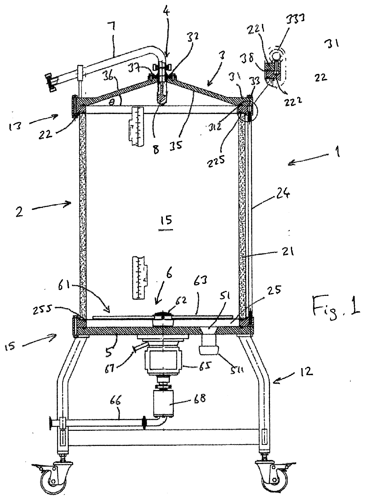
[0032]The separation apparatus 1 in this embodiment is an expanded bed separation column with a column tube 2. In this example the column tube is 600 mm in internal diameter. It has a cylindrical tube side wall 21 made of transparent acrylic 40 mm thick, held between an annular metal top flange 22 at the top 13 of the apparatus and an annular metal bottom flange 25 at the base 15. The base 15 is mounted on a conventional mobile stand (skid) 12 providing working clearance beneath the column tube 2. In a known manner, the top and bottom edges of the column tube wall 21 seal against respective downward and upward surfaces of the top and bottom flanges 22,25 with elastomeric sealing members 225,255 between. A discrete base plate 5 and top cap plate 3 close off the bottom and top ends of the tube. Like the top and bottom flanges, the base plate and top cap are of stainless steel. The base plate 5 is flat and fits sealingly—with the aid of a further elastomeric seal ring—against the under...


PUM

PropertyMeasurementUnit
angleaaaaaaaaaa
angleaaaaaaaaaa
angleaaaaaaaaaa

Abstract

A separation column for expanded bed adsorption comprises a column tube (2), a base (15) carrying an inlet rotor structure (6) for pumping in process liquid, and a top cap (3). The top cap (3) is conical in form, and has a peripheral flange 31 by which it is rigidly fixed to the top edge flange (22) of the column tube (2). The angle of the convergent interior surface (35) of the conical top cap (3) may be between 10 and 25°. A vortex-inhibitor component (8) projects down below the outlet structure (4) at the top of the cap, projecting into the operating space (15) of the column to inhibit rotation of liquid in the column interior. An expanded bed adsorption process is done with upward flow of liquid in the column through a bed of media particles.

Description

CROSS-REFERENCE TO RELATED APPLICATIONS[0001]This application is a continuation of U.S. patent application Ser. No. 15 / 074,017 filed Mar. 18, 2016, which claims the benefit of United Kingdom Patent Application No. 1504695.6 filed Mar. 19, 2015.FIELD OF THE INVENTION[0002]This invention relates to apparatus and methods for separation of substances by chromatography, particularly but not exclusively expanded-bed chromatography.BACKGROUND[0003]Expanded bed or fluidised bed separation processes (often known as EBA: “expanded bed adsorption”) are well known. They are useful for example in the production of biologically-produced molecules e.g. for drugs, vaccines, diagnostic agents or the like. Many such products are produced in cell cultures and they (or their precursors) must be separated from a culture product such as a homogenised broth or slurry which contains insoluble solids such as cell debris as well as contaminants. This solid material cannot pass through a conventional packed (...

Claims


Application Information

Patent Timeline
Patent Type & Authority Applications(United States)
IPC IPC(8): B01D15/18B01D15/22B01D15/26C07K1/22G01N30/60
CPCG01N30/6017C07K1/22B01D15/22B01D15/265G01N30/6004G01N30/56B01D15/1807
Inventor HOFMANN, MARTIN JOHN
Owner BIOTECHFLOW
Why Eureka
Try Eureka