Image forming apparatus

a technology of image forming apparatus and pressing roller, which is applied in the direction of electrographic process apparatus, instruments, optics, etc., can solve the problems of increased water vapor deposited on the pressing roller, increased dew condensation slip, and increased creases of image rubbing and recording material, so as to reduce the degree of unevenness of recording material feeding force and suppress image rubbing. occurrences

Active Publication Date: 2020-01-23
CANON KK
View PDF0 Cites 0 Cited by
  • Summary
  • Abstract
  • Description
  • Claims
  • Application Information

AI Technical Summary

Benefits of technology

[0007]A principal object of the present invention is to provide an image forming apparatus capable of suppressing occurrences of image rubbing and recording material creases by reducing a degree of unevenness of a recording material feeding force in a fixing nip even in the case where unevenness of a print ratio with respect to a widthwise direction in large.

Problems solved by technology

As a result, an amount of the water vapor deposited on the surface of the pressing roller increases, and then in the case where a print ratio of the image is large, the dew condensation slip is more liable to occur.
However, in the case where images largely different in print ratio (area of the image) are formed at different positions, respectively, with respect to a widthwise direction of the recording material, at a large print ratio portion, an amount of water vapor deposited on the pressing roller increases, so that the dew condensation slip is liable to occur.
In the case where one-side slack is conspicuous, a rising portion due to the slack contacts some component part on a recording material feeding path, so that an unfixed toner image on the recording material is disturbed and thus an image defect such as image rubbing occurs.
Further, in the case where the one-side slack is conspicuous and the slack of the recording material cannot be absorbed, the recording material enters the fixing nip in a state in which the recording material is folded, so that recording material creases occur in some instances.

Method used


Image

  • Image forming apparatus
  • Image forming apparatus
  • Image forming apparatus

Examples


first embodiment

(Image Forming Apparatus)

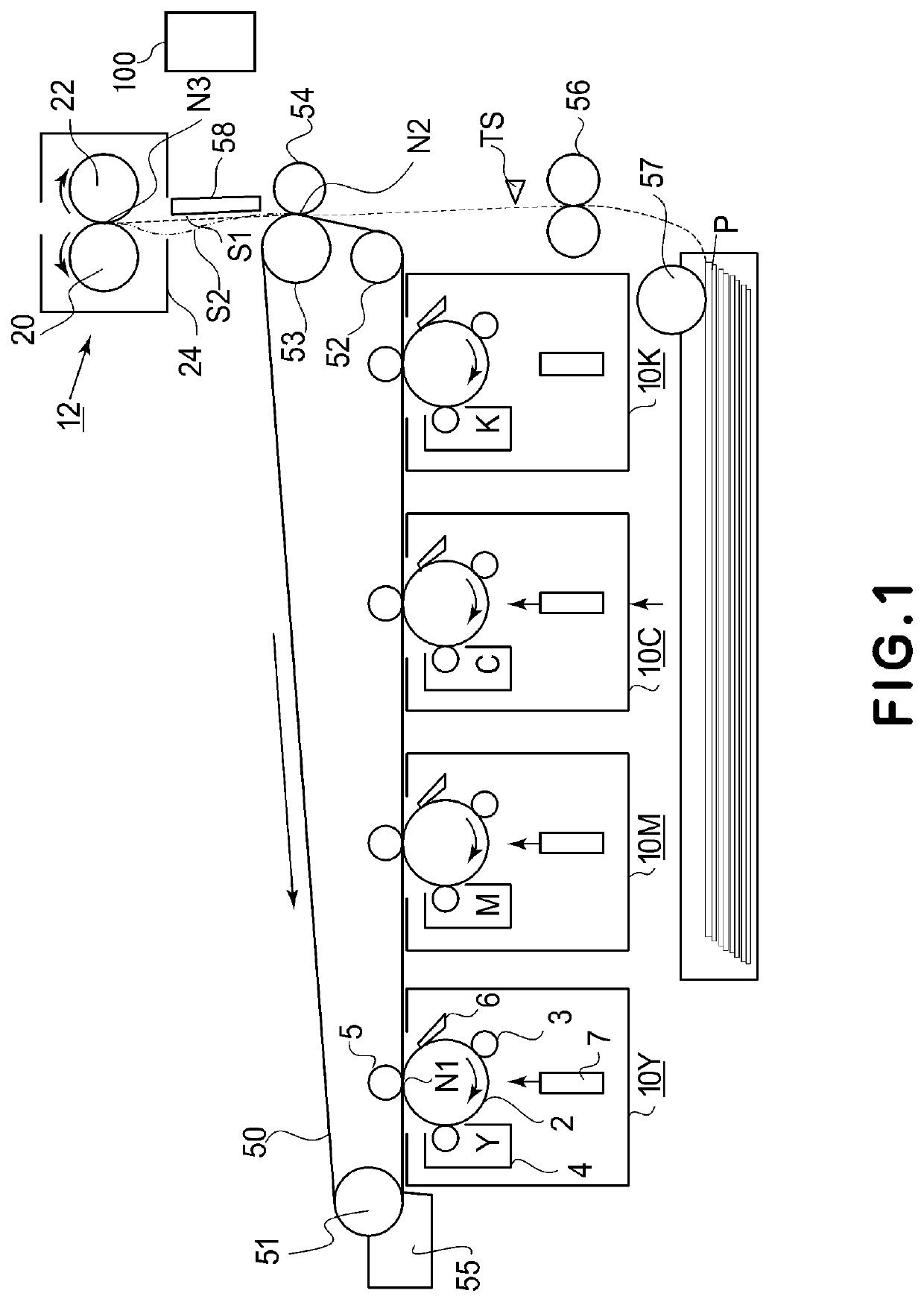
[0023]FIG. 1 is a schematic structural view showing an image forming apparatus according to the present invention. This image forming apparatus is a tandem full-color printer of an electrophotographic type. This image forming apparatus includes four image forming portions (image forming units 10Y, 10M, 10C and 10K) which are disposed in series with certain intervals. In the following, the image forming portion (unit) 10Y for yellow will be described as an example.

[0024]Each of the image forming portions includes a photosensitive drum 2, and at a periphery of the photosensitive drum 2, includes a charging roller 3, a developing device 4, a primary transfer roller 5 and a drum cleaning device 6. Below between the charging roller 3 and the developing device 4, an exposure device 7 is provided. In the respective developing devices 4, yellow toner, magenta toner, cyan toner and black toner are accommodated. The photosensitive drum 2 is rotationally driven at a pr...

second embodiment

[0081]In First Embodiment, the control is carried out so as to increase the sheet interval in the case where the image with the large image unevenness x is detected, whereby an effect of preventing the occurrence of the image rubbing was obtained. However, the control was such that the sheet interval was uniformly increased in the case where the image unevenness x exceeded a certain threshold, and therefore, depending on the magnitude of the image unevenness x, a state in which the sheet interval was increased more than necessary was formed. Therefore, in this embodiment, as the sheet interval increase control, control such that the sheet interval is stepwisely changed depending on the image unevenness x was carried out.

[0082]In First Embodiment, in the case where the image unevenness x exceeded 5.5, control such that the sheet interval was increased to 314 mm was carried out. On the other hand, in this embodiment, depending on an amount of the image unevenness x which exceeded 5.5,...

third embodiment

[0088]In the heaters of the fixing devices described in First and Second Embodiments, a heat generation distribution with respect to the longitudinal direction of the heater was not able to be switched. In this embodiment, an image forming apparatus which includes a heater including a heat generating block divided into a plurality of heat generating blocks with respect to the longitudinal direction (hereinafter, this heater is referred to as a division heater) will be described.

[0089]In the image forming apparatus of this embodiment, depending on acquired image information, the heat generating blocks (heat generating members) of the division heater can be independently controlled. A constitution in which heating is made at a high temperature in a region in which the print ratio with respect to the widthwise direction of the recording material is high and in which heating is made at a low temperature in a region in which the print ratio with respect to the widthwise direction of the ...


PUM


Abstract

An image forming apparatus for forming a toner image on a recording material includes an image forming portion configured to form the toner image on the recording material, a fixing portion including a heater and configured to fix the toner image on the recording material by heating the toner image formed on the recording material, and a controller configured to control the image forming apparatus. When toner images are continuously formed on a plurality of recording materials, the controller sets an interval between a preceding recording material and a subsequent recording material depending on unevenness of a print ratio of the subsequent recording material with respect to a direction perpendicular to a recording material feeding direction of the subsequent recording material.

Description

FIELD OF THE INVENTION AND RELATED ART[0001]The present invention relates to an image forming apparatus, capable of forming an image on a recording material, such as a copying machine, a printer or a facsimile machine, employing an electrophotographic type, for example.[0002]When a toner image transferred onto a recording material at a transfer nip in an image forming portion is heated at a fixing nip downstream of the transfer nip with respect to a recording material feeding direction while nipping and feeding the recording material at the fixing nip, water vapor generates in the case of the recording material taking up moisture. When dew forms on a surface of a rotatable member (pressing roller), a frictional force with a follower rotatable member or the recording material lowers, so that a phenomenon that the recording material slips (so-called dew condensation slip) occurs. Such a phenomenon has been known.[0003]The occurrence of the dew condensation slip is influenced by an ima...

Claims


Application Information

Patent Timeline
Patent Type & Authority Applications(United States)
IPC IPC(8): G03G15/20
CPCG03G15/2039G03G15/6564G03G15/657G03G15/2042
Inventor UCHIYAMA, KOJI
Owner CANON KK
Why Eureka
Try Eureka