
Wireless vital sign monitoring

Active Publication Date: 2020-01-30
AGIS AUTOMATISERING BV
View PDF0 Cites 3 Cited by
  • Summary
  • Abstract
  • Description
  • Claims
  • Application Information

AI Technical Summary

Benefits of technology

The invention relates to a method for measuring vital signs using a small wearable device that is designed to conserve energy and minimize interference with patient movement. The device has a motion sensor that detects the user's movements and, only when there is no significant movement, an opto-electronic sensor is activated to measure the optical response signals. This reduces energy consumption and avoids interference with motion noise, resulting in accurate and reliable vital signs readings. The device can be used in low care hospital wards where reliability is more important than showing the most recent values or urgent alarms. In summary, the invention is designed to provide a more effective and efficient means of measuring vital signs for patient care.

Problems solved by technology

One problem with the proposed system is that vital sign sensors, in particular optical vital sign sensors, are very sensitive to noise and movements.
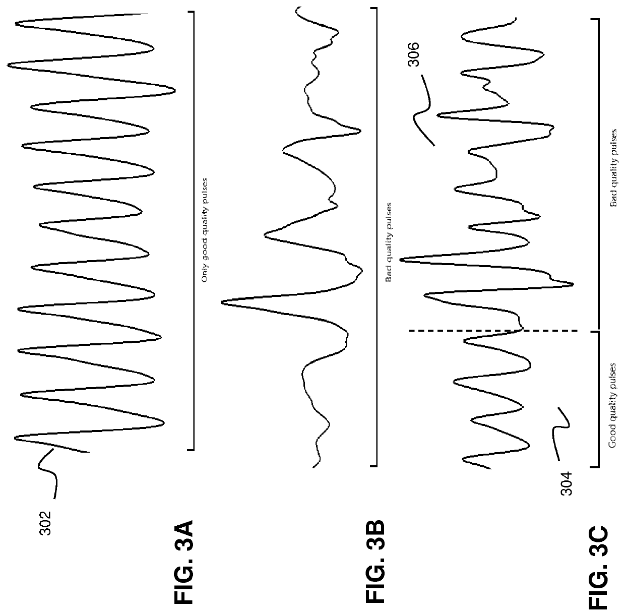
For example, when measuring heart rate and / or oxygen saturation on the basis of an optical measuring device, e.g. an opto-electronic device comprising one or more LEDS and photodiodes, small abrupt movements by a person in an “inactive state” (e.g. sitting or lying) may induce motion artefacts in the measured data, which make the data unreliable or even useless.
In high-care (intensive care) vital sign monitoring, it is known that movements of a patient are a dominant source for causing errors and deviations in the measured signal.
Such data processing techniques however require a substantial amount of processor resources and associated power consumption that is not compatible with the requirement that a low-care wireless measuring device should be a small wearable, low-power measuring device.
A problem related to this prior art system is that tissue motion signal detected by the capacitive sensor may be a combination of different signals: blood movement within tissue, physical movement of tissue and / or changes in pressure / orientation of the capacitive sensor on the tissue.
A separation of the tissue motion signal into the different individual signals requires data processing, leading to an estimate of the physical movement which is not very accurate.
The capacitive sensor used in the system is not able to detect physical motion of a user in three dimensions.
Such scheme is not particular efficient in terms of power consumption.

Method used


Image

  • Wireless vital sign monitoring
  • Wireless vital sign monitoring
  • Wireless vital sign monitoring

Examples


Embodiment Construction

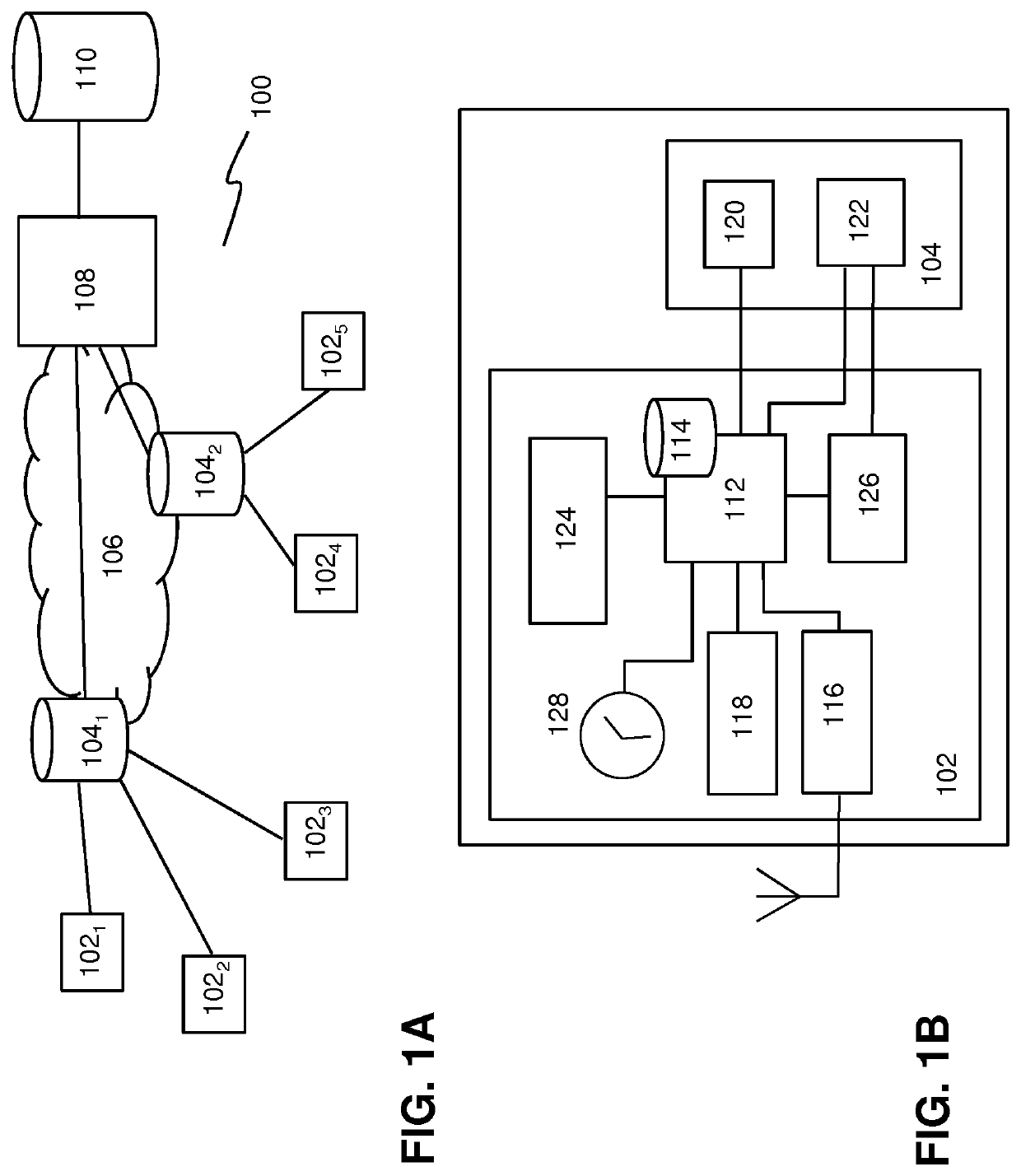
[0055]The embodiments in this disclosure described low-care wireless vital sign monitoring systems and wireless low-power vital sign measuring devices for use in such systems. The wireless vital sign measuring devices provide accurate determination of vital sign parameters for use in low-care vital sign monitoring. The measuring devices are adapted to provide low-power data acquisition and reliable determination of vital sign parameters, which are robust against noise, in particular against motion-induced noise.

[0056]FIGS. 1A and 1B depict schematics a low-care vital sign monitoring system and a wireless vital sign measuring device for use in such monitoring system according to various embodiments of the invention. In particular, FIG. 1A depicts a low-care vital sign monitoring system 100 comprising a plurality of wireless vital sign measuring devices 1021-5 (hereafter in short also referred to as measuring devices) that are configured to wirelessly communicate with one or more base...


PUM


Abstract

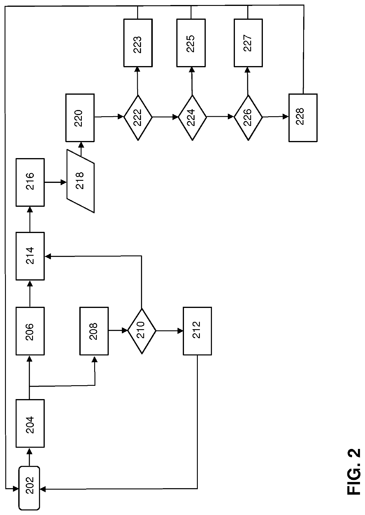
A method of determining one or more vital sign parameters by a wireless vital-sign measurement device comprises: measuring motion information of a user wearing the wireless measurement device, the measurement device being in the idle mode in which at least one opto-electronic sensor in the measurement device is deactivated; switching the measurement device in an active mode if the motion information is below a predetermined threshold, wherein in the active mode the at least one opto-electronic sensor is activated; during a predetermined measuring period, exposing part of a skin tissue of the user to light and measuring one or more optical response signals associated with the exposed skin tissue and the motion sensor measuring motion information associated with movements of the user; and, selecting or rejecting one or more pulses in the one or more optical response signals on the basis of the motion information measured during the measuring period and determining one or more vital sign parameters on the basis of the one or more selected pulses.

Description

FIELD OF THE INVENTION[0001]The invention relates to wireless vital sign monitoring, and, in particular, though not exclusively, to methods and systems for wireless vital sign monitoring, a measuring device adapted for wireless vital sign monitoring, and a computer program product for executing such methods.BACKGROUND OF THE INVENTION[0002]Currently in hospitals multiple vital signs of patients in high-care wards are being monitored continuously twenty-four hours a day. In contrast, when a patient is in a low-care hospital ward, only selected vital signs such as pulse, oxygen saturation (SpO2), and temperature are monitored and this is done manually at 6-8 hour time intervals using spot measurements (usually referred to as a spot check). Typically, the measurements are manually entered into a (electronic) patient dossier. Patient safety can be improved, while working more efficiently at the same time when an automated trend of multiple vital signs could be measured.[0003]US2015 / 0305...

Claims


Application Information

Patent Timeline
IPC IPC(8): A61B5/00A61B5/11
CPCA61B5/1118A61B5/0002A61B2562/0219A61B5/6816A61B5/6838A61B2560/0209A61B5/6843A61B5/721A61B5/02416
Inventor GRASSERE, STEFANUS HENDRIKUS HUBERTINABEUDEL, JORIS CHRISTIANVAN FULPEN, MAARTEN-JAN
Owner AGIS AUTOMATISERING BV
Learn More