Hybrid vehicle control device

a control device and hybrid technology, applied in the direction of gearing control, gearing element, belt/chain/gearing, etc., can solve the problems of hydraulic pressure hunting, limited primary pressure reduction, and excessive primary pressure reduction margin

Active Publication Date: 2020-01-30
JATCO LTD +1
View PDF0 Cites 3 Cited by
  • Summary
  • Abstract
  • Description
  • Claims
  • Application Information

AI Technical Summary

Benefits of technology

[0009]This configuration serves to prevent hunting of hydraulic pressure where the primary pressure and the secondary pressure in

Problems solved by technology

However, the reduction of the primary pressure is limited, because a primary pressure lower limit is set for the primary pressure.
However, if the primary pressure lower limit is set for expediting the low speed position return speed independently of the deceleration, it is possible that the margin of reduction of the primary pressure i

Method used


Image

  • Hybrid vehicle control device
  • Hybrid vehicle control device
  • Hybrid vehicle control device

Examples


first embodiment

[0020]First, the following describes configuration of the continuously variable transmission control device according to the first embodiment, which is applied to an FF hybrid vehicle where a belt-type continuously variable transmission is mounted in a driveline. The following describes configuration of the continuously variable transmission control device according to the first embodiment, separately in sections [Whole System Configuration], [Configuration of Shift Control of Belt-Type Continuously Variable Transmission], and [Configuration of Process of Low Speed Position Return Expediting Control]. For description of the first and second embodiments, a low speed position is referred as “Low” and a high speed position is referred as “High”.

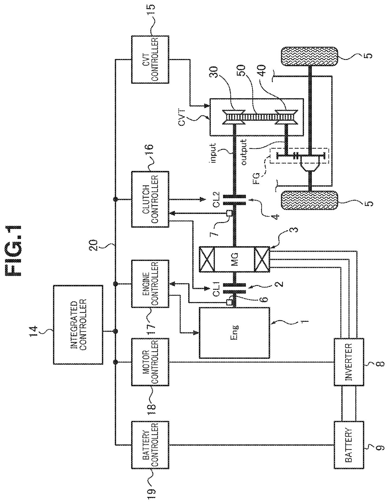
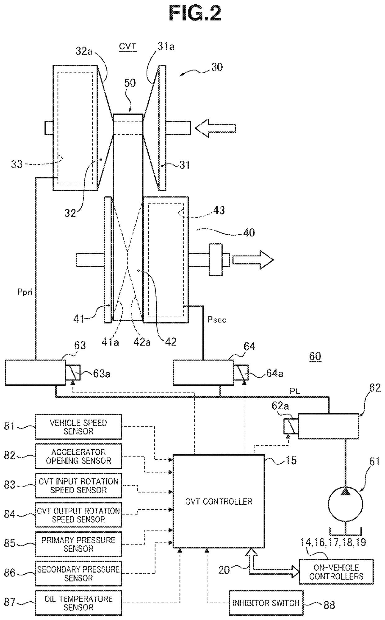
[0021][Whole System Configuration]FIG. 1 is a whole system diagram showing the FF hybrid vehicle to which the control device for the belt-type continuously variable transmission is applied. The following describes whole system configuration of t...

second embodiment

[0122]The second embodiment is configured to set the secondary pressure lower limit equal to the trigger threshold value, whereas the first embodiment is configured to set the relationship of the trigger threshold value>the secondary pressure lower limit.

[0123]The following describes configuration of a continuously variable transmission control device according to the second embodiment, which is applied to an FF hybrid vehicle as in the first embodiment. Sections [Whole System Configuration] and [Configuration of Shift Control of Belt-Type Continuously Variable Transmission] for the second embodiment are the same as in the first embodiment, and description thereof and related drawings are omitted. The following describes a section [Configuration of Process of Low Speed Position Return Expediting Control] for the second embodiment.

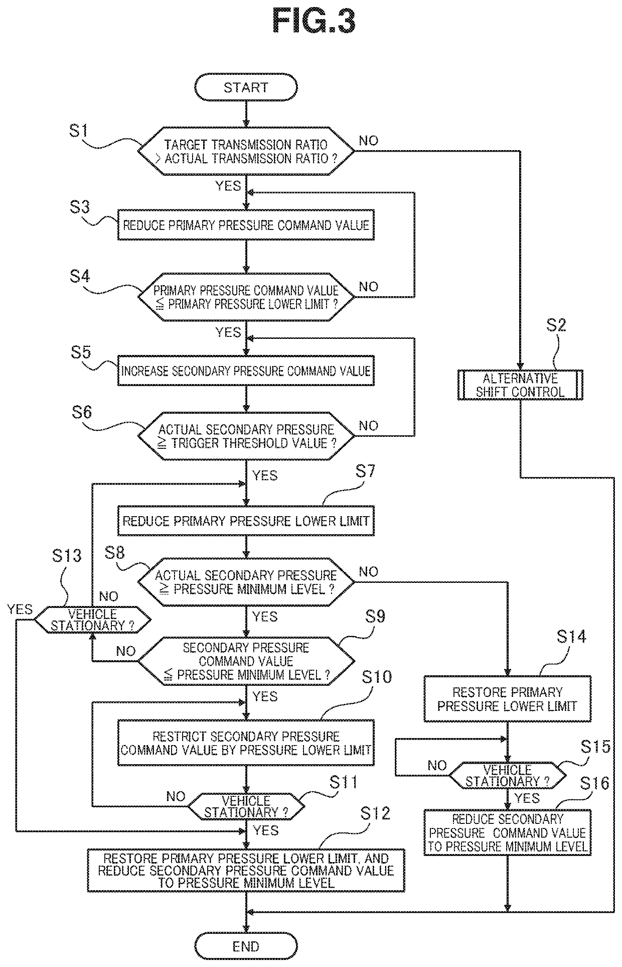
[0124][Configuration of Process of Low Speed Position Return Expediting Control]FIG. 8 is a flow chart showing a flow of low speed position return expediti...


PUM


Abstract

For a hybrid vehicle including an engine, a motor generator, and a belt-type continuously variable transmission, a controller performs a low speed position return expediting control in response to a downshift request accompanying deceleration. During the low speed position return expediting control, the controller increases a differential pressure between a primary pressure and a secondary pressure and cause a downshift toward a lowest speed position transmission ratio by reducing the primary pressure, and further reduces the primary pressure when the secondary pressure becomes greater than or equal to a trigger threshold value during the downshift; and terminates the low speed position return expediting control when an actual secondary pressure decreases to a secondary pressure minimum level. The controller further sets a secondary pressure lower limit higher than the secondary pressure minimum level during the low speed position return expediting control.

Description

TECHNICAL FIELD[0001]The present invention relates to a control device for a continuously variable transmission which is configured to perform a low speed position return expediting control for increasing a differential pressure between a primary pressure and a secondary pressure at least by reducing the primary pressure in response to a downshift request accompanying a deceleration.BACKGROUND ART[0002]Conventionally, a belt-type continuously variable transmission is known which is configured to perform a low speed position return expediting control for expediting a speed of progress of shifting to a lowest speed position (i.e. low speed position return speed) by increasing a differential pressure between a primary pressure and a secondary pressure by reducing the primary pressure in response to a downshift request accompanying a deceleration. However, the reduction of the primary pressure is limited, because a primary pressure lower limit is set for the primary pressure. Accordingl...

Claims


Application Information

Patent Timeline
IPC IPC(8): F16H61/662B60W10/107
CPCB60W2710/1083F16H2061/0462B60W10/107F16H61/66272F16H2061/66281F16H59/18F16H59/40F16H59/42F16H59/44F16H59/72F16H61/02F16H61/662F16H61/66259F16H2059/683F16H2061/6605F16H59/68
Inventor TOKOI, HIROYUKIYONEDA, KENJIMIYAISHI, HIRONORI
Owner JATCO LTD
Why Eureka
Try Eureka