Thermoelectric device having circuitry with structural rigidity

Active Publication Date: 2020-01-30
GENTHERM INC
View PDF0 Cites 7 Cited by
  • Summary
  • Abstract
  • Description
  • Claims
  • Application Information

AI Technical Summary

Benefits of technology

[0005]In certain embodiments, a thermoelectric module for thermally conditioning a component is provided. The module comprises first and second heat spreaders spaced apart from one another and configured to respectively provide cold and hot sides and to be mechanically coupled together by at least one fastener. The module further comprises a material arranged between the first and second heat spreaders. The module further comprises a thermoelectric device operatively engaged with the first and second heat spreaders. The thermoelectric device comprises a thermally conductive first plate and at least one thermoelectric sub-assembly. The first plate comprises a layer comprising a plurality of electrically conductive first portions and a plurality of electrically insulating

Problems solved by technology

Power electronics and other electrical devices, such as batteries, can be sensitive to overheating, cold temperatures, extreme temperatures, and operating temperature limits.
The performance of such devices may be diminished, sometimes severely, when the devices are operated outside of recommended temperature ranges.
In semiconductor devices, integrated circuit dies can ov

Method used


Image

  • Thermoelectric device having circuitry with structural rigidity
  • Thermoelectric device having circuitry with structural rigidity
  • Thermoelectric device having circuitry with structural rigidity

Examples


Embodiment Construction

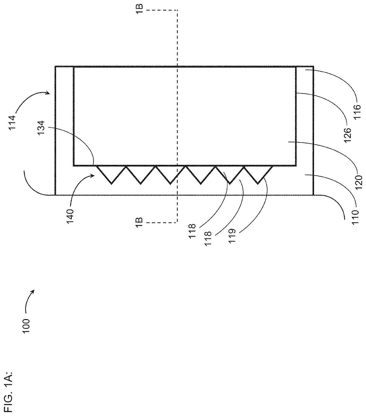
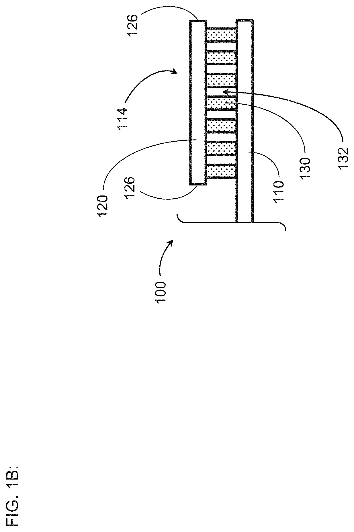
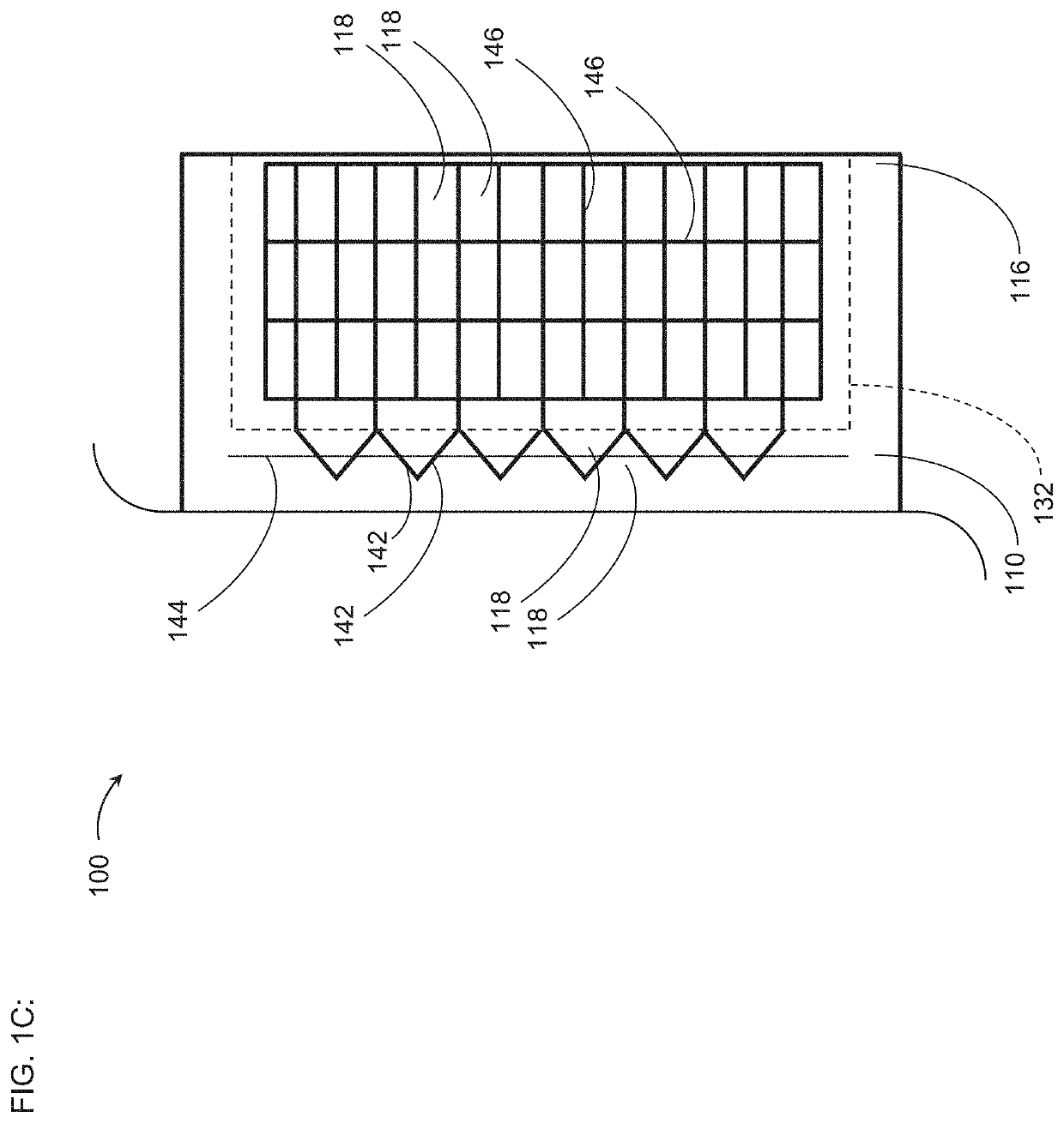
[0024]FIG. 1A schematically illustrates a top view of an example thermoelectric device 100 in accordance with certain embodiments described herein. FIG. 1B schematically illustrates a cross-sectional view of the example thermoelectric device 100 of FIG. 1A. FIG. 1C schematically illustrates a top view of an example first plate 110 in accordance with certain embodiments described herein.

[0025]The thermoelectric device 100 of FIGS. 1A-1B comprises a thermally conductive first plate 110 and at least one thermoelectric sub-assembly 114 comprising a thermally conductive second plate 120 and a plurality of thermoelectric (“TE”) elements 130. As shown schematically in FIGS. 1A and 1C, the first plate 110 comprises a layer 116 comprising a plurality of electrically conductive first portions 118 and a plurality of electrically insulating second portions 119 separating the first portions 118 from one another. The plurality of TE elements 130 is in a region 132 bounded by and including (e.g., ...


PUM


Abstract

A thermoelectric device includes a thermally conductive first plate and at least one thermoelectric sub-assembly. The first plate has a layer with a plurality of electrically conductive first portions and a plurality of electrically insulating second portions separating the first portions from one another. The at least one thermoelectric sub-assembly includes a thermally conductive second plate and a plurality of thermoelectric elements in a region between the first plate and the second plate. The plurality of thermoelectric elements is in electrical communication with the plurality of electrically conductive portions of the first plate, in electrical communication with electrically conductive portions of the second plate, and in thermal communication with the first plate and the second plate. The plurality of electrically insulating second portions includes a plurality of segments at least partially outside the region, the segments configured to avoid degradation of a structural rigidity of the first plate.

Description

INCORPORATION BY REFERENCE TO ANY PRIORITY APPLICATIONS[0001]Any and all applications for which a foreign or domestic priority claim is identified in the Application Data Sheet as filed with the present application are incorporated by reference and made a part of this specification.BACKGROUNDField[0002]This application relates to thermoelectric devices and modules used for thermal management of components and / or systems, including but not limited to batteries.Description of the Related Art[0003]Power electronics and other electrical devices, such as batteries, can be sensitive to overheating, cold temperatures, extreme temperatures, and operating temperature limits. The performance of such devices may be diminished, sometimes severely, when the devices are operated outside of recommended temperature ranges. In semiconductor devices, integrated circuit dies can overheat and malfunction. In batteries, including, for example, batteries used for automotive applications in electrified or...

Claims


Application Information

Patent Timeline
IPC IPC(8): H01L35/32H01L35/04H01L35/30H01L35/34
CPCH01L35/32H01L35/30H01L35/04H01L35/34H10N10/81H10N10/80H10N10/13H10N10/01H10N10/17
Inventor BÜCK, WERNER
Owner GENTHERM INC
Why Eureka
Try Eureka