
Method and device for uplink power control

a power control and uplink technology, applied in power management, wireless communication, transmission path sub-channel allocation, etc., can solve the problems of inability to guarantee the performance of uci transmission, inability to obtain inability to achieve good frequency diversity gain, etc., to achieve effective power control method, and more effective power control of pucch

Active Publication Date: 2020-01-30
SAMSUNG ELECTRONICS CO LTD
View PDF5 Cites 58 Cited by
  • Summary
  • Abstract
  • Description
  • Claims
  • Application Information

AI Technical Summary

Benefits of technology

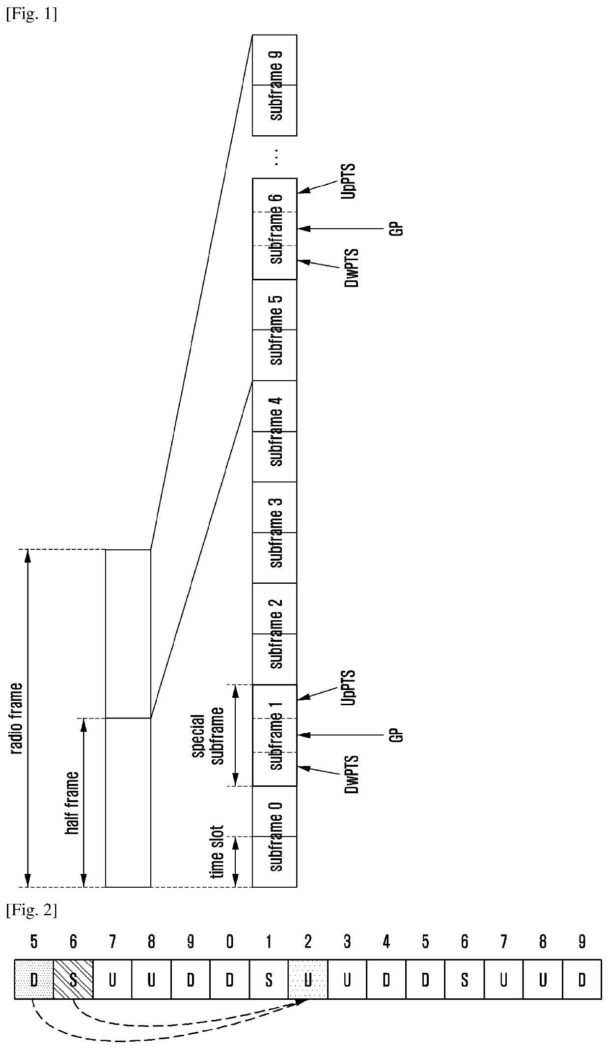
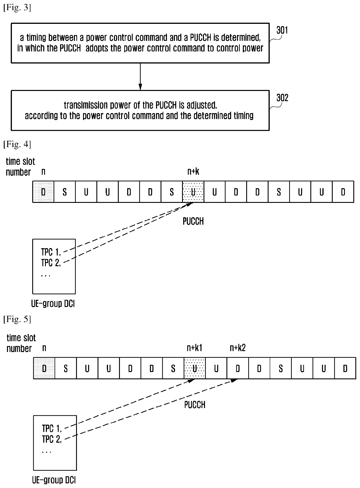
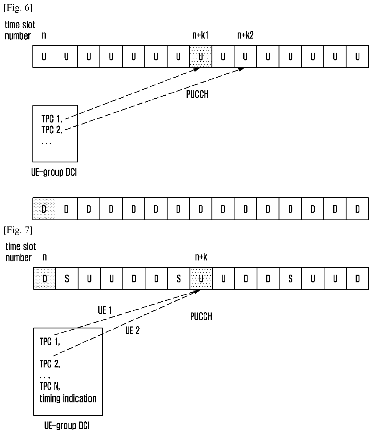
The present patent provides a method and device for more effective power control of the uplink control channel (PUCCH) in wireless communication. If the time slots for transmitting PUCCH and a power control command are different, this method ensures better power control for PUCCH. Additionally, when there is no known timing for the acknowledgement of downlink data, this method helps determine the timing between the power control command and PUCCH. Overall, this technology improves the efficiency and reliability of wireless communication.

Problems solved by technology

When different waveforms are used for transmitting UCI by a user equipment (UE), good frequency diversity gain cannot be obtained if an inappropriate transmission mode is adopted since different waveforms have different peak-to-average power ratios (PAPRs).
Therefore, performance of data transmission may be affected and performance of UCI transmission cannot be guaranteed.
The rapid development of information industry, particularly the increasing demand from the mobile Internet and the Internet of Things (IoT), brings about unprecedented challenges in the future mobile communications technology.
Therefore, the measurement and handover method based on the cell-specific reference signal used in the LTE / LTE-A system can no longer be applied to the requirements of the future 5G radio communication system, and a new measurement and handover method needs to be designed for the 5G radio communication system to take place of the role of cell-specific reference signal in LTE / LTE-A system.

Method used


Image

  • Method and device for uplink power control
  • Method and device for uplink power control
  • Method and device for uplink power control

Examples


example 9

[0458]In this example, there is no correlation between a transmission waveform for a PUCCH determined by a UE and a transmission waveform for a PUSCH determined by the UE. The UE determines a transmission waveform for a PUSCH according to type of the PUSCH.

[0459]A PUSCH may be classified as a first type of PUSCH or a second type of PUSCH according to whether downlink control information (DCI) used for scheduling the PUSCH by the base station supports spatial multiplexing or not. The DCI corresponding to the first type of PUSCH supports spatial multiplexing, and the DCI corresponding to the second type of PUSCH does not support spatial multiplexing.

[0460]The UE determines the transmission waveform for the first type of PUSCH to be CP-OFDM and determines the transmission waveform for the second type of PUSCH according to dynamic indication information from the base station. If the dynamic indication information from the base station is physical layer signaling, one bit therein may be ...

example 10

[0461]Special situations will be described in this example.

[0462]If a UE determines that CP-OFDM waveform is used for a PUSCH, the PUSCH will not use frequency hopping within a slot. Specifically, because CP-OFDM allows transmission resource for the PUSCH to be distributed discretely in frequency domain, sufficient frequency-domain diversity gain can be obtained and it is not necessary to use frequency hopping to obtain additional frequency-domain diversity gain.

[0463]If the UE determines that SC-FDM waveform is used for a PUSCH, the PUSCH can use frequency hopping within a slot. Specifically, because transmission resource for the PUSCH is substantially continuous in frequency-domain, sufficient frequency-domain diversity gain cannot be obtained and it may be necessary to use frequency hopping within a slot to obtain additional frequency-domain diversity gain.

[0464]As described hereinbefore, step 102 comprises transmitting UCI and data based on the determined transmission waveform f...

example 5

[0481]A process of transmitting UCI and data by a UE in the case that the UE determines that the CP-OFDM waveform will be used to transmit the PUSCH and the UE can transmit PUCCH and PUSCH simultaneously (i.e., within a same slot), is described in this example. In this example, the UE can transmit the PUCCH and the PUSCH simultaneously in one or more serving cells.

[0482]A UE may transmit UCI and data either on a PUCCH or on a PUSCH. The UE simultaneously transmits a plurality of PUCCHs in one subframe, which may comprise respective PUCCHs for HARQ-ACK, for CSI and for SR. Specifically, if there are a plurality of available PUCCHs for the UE, of which some are exclusive PUCCHs and others are shared PUCCHs, the UE transmits UCI and data on the exclusive PUCCHs, transmits UCI on the shared PUCCHs and transmits UCI and data on the PUSCH.

[0483]For example, the UE may take UCI and data to be transmitted as a whole and distributes them on the PUSCH and one or more exclusive PUCCHs so as to...


PUM


Abstract

The present disclosure relates to a communication method and system for converging a 5th-Generation (5G) communication system for supporting higher data rates beyond a 4th-Generation (4G) system with a technology for Internet of Things (IoT). The present disclosure may be applied to intelligent services based on the 5G communication technology and the IoT-related technology, such as smart home, smart building, smart city, smart car, connected car, health care, digital education, smart retail, security and safety services. The present disclosure provides a method for uplink power control, which is applied to a User Equipment (UE), and the method includes: determining a timing between a power control command and a Physical Uplink Control Channel (PUCCH), which adopts the power control command to control power. The present disclosure also provides a corresponding device.

Description

TECHNICAL FIELD[0001]The present disclosure relates to wireless communication technologies, and more particularly, to a method and a device for uplink power control, to a method and a user equipment (UE) for transmitting uplink control information (UCI), to a method and a UE of bandwidth part (BWP) switching, to a method and apparatus for measuring cell, a method and apparatus for handover, to a method and a device for reporting Channel State Information (CSI).BACKGROUND ART[0002]To meet the demand for wireless data traffic having increased since deployment of 4G communication systems, efforts have been made to develop an improved 5G or pre-5G communication system. Therefore, the 5G or pre-5G communication system is also called a ‘Beyond 4G Network’ or a ‘Post LTE System’. The 5G communication system is considered to be implemented in higher frequency (mmWave) bands, e.g., 60 GHz bands, so as to accomplish higher data rates. To decrease propagation loss of the radio waves and increa...

Claims


Application Information

Patent Timeline
Patent Type & Authority Applications(United States)
IPC IPC(8): H04W52/14H04W52/36H04W72/04H04W80/08H04L5/00
CPCH04W80/08H04L5/0092H04W52/146H04W52/36H04W72/042H04L27/2636H04L27/2646H04W52/281H04W52/325H04W52/346H04L5/0044H04L5/0053H04W52/16H04W52/32H04L27/2601H04W72/23
Inventor FU, JINGXINGQIAN, CHENZHANG, YINGJIEYU, BINXIONG, QISUN, FEIFEI
Owner SAMSUNG ELECTRONICS CO LTD
Learn More