
Double-flow type volute casing having structure for changing direction of flow in turbine inlet

a technology of volute casing and turbine blade, which is applied in the direction of reaction engines, machines/engines, stators, etc., can solve the problems of reducing power production efficiency, partially fluctuating movement of turbine blades, and excessive fluid pressure applied

Active Publication Date: 2020-02-06
DONG HAE ENG
View PDF0 Cites 2 Cited by
  • Summary
  • Abstract
  • Description
  • Claims
  • Application Information

AI Technical Summary

Benefits of technology

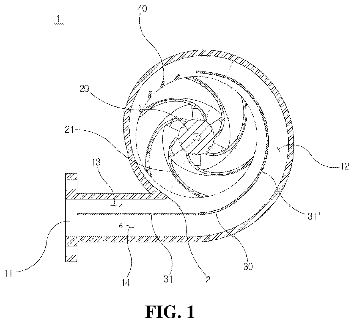
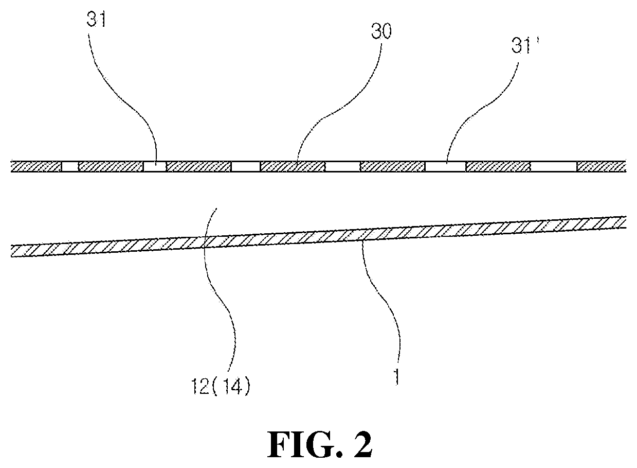
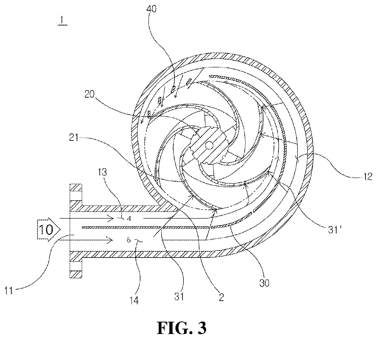
The present invention provides a double-flow type volute casing for a hydraulic turbine that has a structure for changing the direction of flow in a turbine inlet. This structure includes a partition plate that surrounds the turbine and has multiple flow-rate adjustment holes. High-pressure fluid flows in the outer flow channel is introduced into the inner flow channel and directed perpendicularly to the turbine blades, reducing energy loss and imbalanced variation of torque applied to the turbine blades, preventing vibration and increasing the rotational force. This results in improved performance and longer lifespan of the hydraulic turbine through stable driving.

Problems solved by technology

In the conventional volute casing described above, however, excessive pressure of the fluid is applied in a rotary section into which the fluid is initially introduced.
As a result, loss in the movement of the turbine blades is partially fluctuated, which is considerably problematic in that power production efficiency is reduced and the defect rate of the turbine is increased.
The above partition plate structure places great importance simply on partitioning the volute; however, pressure is reduced, and thus performance is deteriorated.
In small-sized products, however, the flow of the fluid is disturbed.

Method used


Image

  • Double-flow type volute casing having structure for changing direction of flow in turbine inlet
  • Double-flow type volute casing having structure for changing direction of flow in turbine inlet
  • Double-flow type volute casing having structure for changing direction of flow in turbine inlet

Examples


Embodiment Construction

[0017]It should be noted that terms or words used in this specification and the claims are not to be interpreted as having ordinary and dictionary-based meanings but as having meanings and concepts coinciding with the technical idea of the present invention based on the principle that the inventors may appropriately define the concepts of the terms in order to explain the invention in the best method.

[0018]Consequently, the embodiments described in this specification with reference to the accompanying drawings are merely the most preferred embodiments, and do not cover all technical ideas of the present invention, and therefore it should be understood that there may be various equivalents and modifications capable of substituting for the embodiments at the time of filing of the present application.

[0019]Hereinafter, a preferred embodiment of the present invention will be described in detail with reference to the accompanying drawings.

[0020]FIG. 1 is a general view showing a double-f...


PUM


Abstract

Disclosed is a Francis turbine, and more particularly a double-flow type volute casing having a structure for changing the direction of flow in a turbine inlet, wherein a partition plate for partitioning a volute defined in the casing into an inner flow channel and an outer flow channel is provided so as to surround a turbine, the ratio in sectional area of the inner flow channel to the outer flow channel in a volute inlet, into which a fluid is introduced, is 4:6, a plurality of flow-rate adjustment holes is formed in the partition plate so as to be arranged at a gradually decreasing interval such that a high-pressure fluid flowing in the outer flow channel is introduced into the inner flow channel and the fluid flowing in the inner flow channel is directed perpendicularly to the turbine blades, in order to minimize the amount of energy that is lost and to reduce imbalanced variation of torque applied to the turbine blades, whereby it is possible to prevent the generation of vibration and to obtain high rotational force based on the guarantee of stable output, and therefore it is possible to improve the performance of a hydraulic turbine and to increase the lifespan of the hydraulic turbine through the stable driving thereof.

Description

BACKGROUND OF THE INVENTIONField of the Invention[0001]The present invention relates to a volute casing, and more particularly to a double-flow type volute casing having a structure for changing the direction of flow in a turbine inlet, wherein pressure is uniformly applied to turbine blades in order to prevent the movement of the turbine blades and thus to realize stable rotational force of the turbine blades, whereby it is possible to improve the performance of the turbine blades and to increase the lifespan of the turbine blades.Description of the Related Art[0002]In general, a Francis turbine generator is configured to have a structure in which a generator for producing electricity and a hydraulic turbine, which is a rotary machine for converting the potential energy of water into mechanical energy, are installed at upper and lower positions along the same vertical line such that the generator produces electricity using the rotational force received from the hydraulic turbine.[0...

Claims


Application Information

Patent Timeline
IPC IPC(8): F01D17/12F01D9/02
CPCF01D17/12F01D9/026F03B3/02F03B3/186Y02E10/20
Inventor SON, YOUNG
Owner DONG HAE ENG
Learn More