Display device

a display device and display screen technology, applied in the field of display devices, can solve the problems of not being widely used as a screen with a speckle reduction function, difficult for an observer to directly observe an image projected on the screen, and difficulty in increasing the siz

Inactive Publication Date: 2020-02-06
DAI NIPPON PRINTING CO LTD
View PDF5 Cites 0 Cited by
  • Summary
  • Abstract
  • Description
  • Claims
  • Application Information

AI Technical Summary

Benefits of technology

[0004]As another method for reducing speckle, it is considered that a screen in which the diffusion characteristic changes over time is also effective. Here, Patent Literature 2 proposes a screen formed by electronic paper. In the screen of Patent Literature 2, the reflectance changes in accordance with an irradiation position of image light irradiated by the raster scan method. In Patent Literature 2, speckle reduction can be realized while a normal projector is used, by changing the diffusion characteristic of the screen over time. Further, it can be said that it is extremely useful in that speckle can be reduced in combination with a projector that cannot employ the technique of the Cited Literature 1 such as a raster scan type projector.
[0007]The present disclosure provides a display device that makes speckles on a screen difficult to be visually recognized and allows an observer to easily observe an image projected on the screen easily.
[0011]a first optical system that guides transmitted light or diffused light of the screen to an observing direction of an observer and allows an observer to observe a real image or a virtual image of an image projected on the screen,
[0028]According to the present disclosure, speckle on a screen is made difficult to be visually recognized and an observer can easily observe an image projected on the screen.

Problems solved by technology

However, the screen disclosed in Patent Literature 2 has a problem that the durability is not sufficient and it is difficult to increase the size.
As a result, it has not been widely used as a screen having a speckle reduction function.
In addition, when the screen size and installation location are limited, it is conceivable that it is difficult for an observer to directly observe an image projected on the screen, but Patent Literatures 1 and 2 do not disclose a solution for this point at all.

Method used


Image

  • Display device
  • Display device
  • Display device

Examples


Embodiment Construction

[0064]An embodiment of the present disclosure will be described below with reference to drawings. Note that, for the convenience of illustration and easiness of understanding, the reduced scale and the aspect ratio, and the like are changed from the actual object and exaggerated in the drawings attached to the specification.

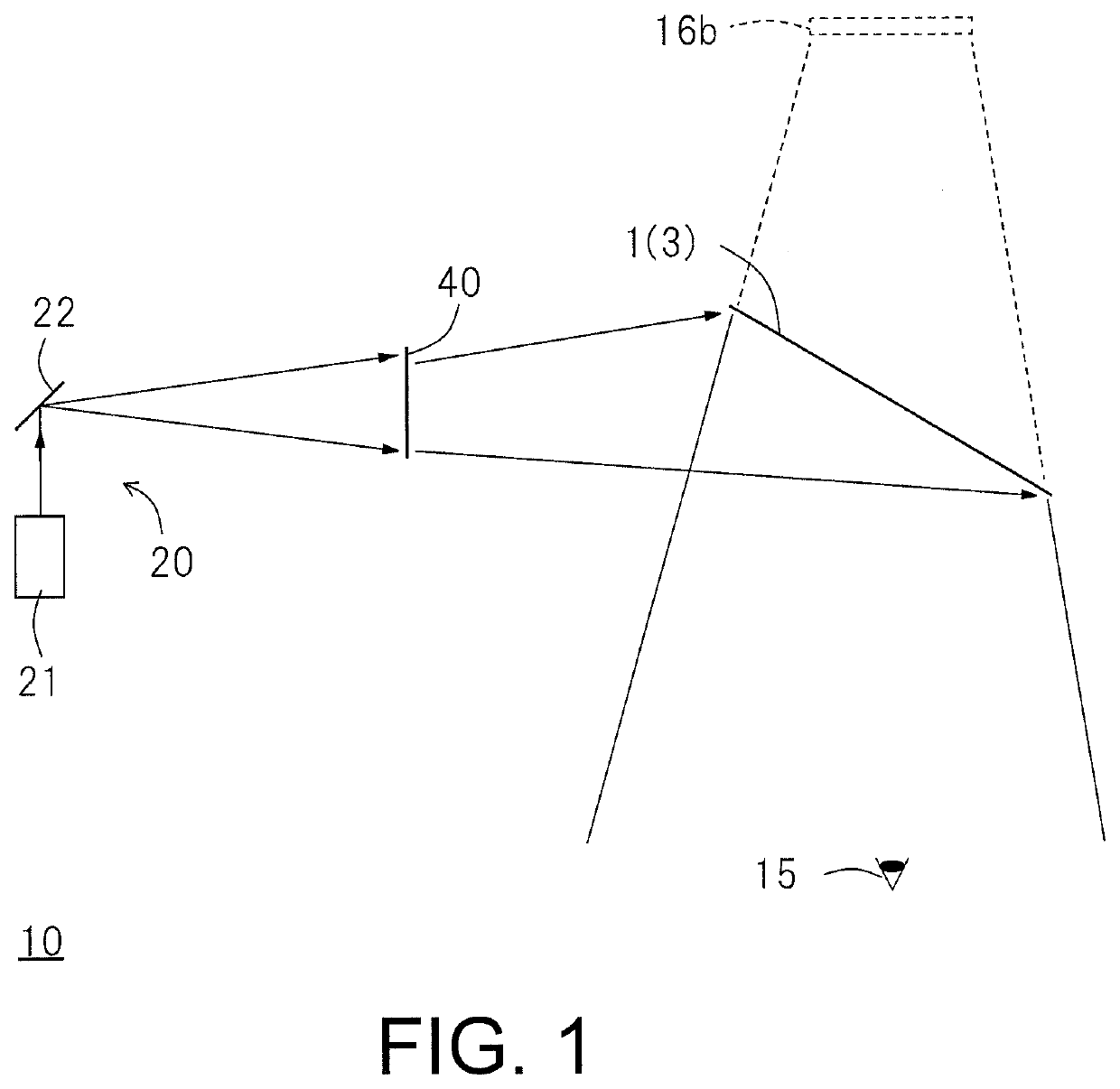
[0065]FIG. 1 is a diagram showing a display device 10 according to an embodiment of the present disclosure. The display device 10 of FIG. 1 includes a projector 20 that emits coherent light, a screen 40 that projects the coherent light emitted from the projector 20, and a first optical system 1. As will be described later, the screen 40 can change a diffuse wave front of emission light over time so that speckle can be made inconspicuous.

[0066]The projector 20 projects light for forming an image, that is, image light onto the screen 40. In the illustrated example, the projector 20 includes a coherent light source 21 that oscillates coherent light, and a scanning d...


PUM

PropertyMeasurementUnit
transmittanceaaaaaaaaaa
wavelength rangeaaaaaaaaaa

Abstract

To provide a display device that makes speckles on a screen difficult to be visually recognized and allows an observer to easily observe an image projected on the screen easily. A display device includes a projector that emits coherent light, a screen that projects the coherent light emitted from the projector, and a first optical system that guides transmitted light or diffused light of the screen to an observing direction of an observer, and allows an observer to observe a real image or a virtual image of an image projected on the screen. The screen includes a plurality of particles including a first portion and a second portion, a particle layer having a plurality of particles, electrodes for applying a voltage to the particle layer to generate an electric field for driving the particles of the particle layer.

Description

TECHNICAL FIELD[0001]The present disclosure relates to a display device including a projector and a screen.BACKGROUND ART[0002]A projector using a coherent light source has been widely used (see Patent Literature 1: WO 2012 / 033174 A, Patent Literature 2: JP 2008-310260 A). Typically, laser light oscillated from a laser light source is used as coherent light. When image light from a projector is formed by coherent light, speckles are observed on a screen irradiated with the image light. The speckles are recognized as a spot pattern and degrades the display image quality. In Patent Literature 1, for the purpose of reducing speckle, an incident angle of image light incident on each position on a screen is changed over time.[0003]As a result, a scattering pattern without correlation is superimposed on the screen, and speckle can be reduced.SUMMARY OF INVENTION[0004]As another method for reducing speckle, it is considered that a screen in which the diffusion characteristic changes over t...

Claims


Application Information

Patent Timeline
Patent Type & Authority Applications(United States)
IPC IPC(8): G03B21/10G02B26/10G02B5/02G02F1/17G03B21/62G02B27/48G02B27/18G02B27/01G02F1/19
CPCG02F1/17G03B21/10G02B26/10G02B27/01G02B27/18G03B21/62G02B27/48G02B5/0278G02B5/0242G02F1/19H04N9/3129G03B21/56G02B27/0101G02B26/026G02B2027/0145G03B21/562
Inventor KURASHIGE, MAKIOKUBOTA, SHOGOISHIDA, KAZUTOSHINAKATSUGAWA, KAORI
Owner DAI NIPPON PRINTING CO LTD
Why Eureka
Try Eureka