
System and method for automatic closed loop control

a closed loop control and system technology, applied in the field of indexing and controlling networks, can solve the problems of obtaining business-level insight and control over the applications, users and devices in modern networks, and the drawbacks of dedicated hardwar

Active Publication Date: 2020-02-06
VMWARE INC
View PDF0 Cites 16 Cited by
  • Summary
  • Abstract
  • Description
  • Claims
  • Application Information

AI Technical Summary

Benefits of technology

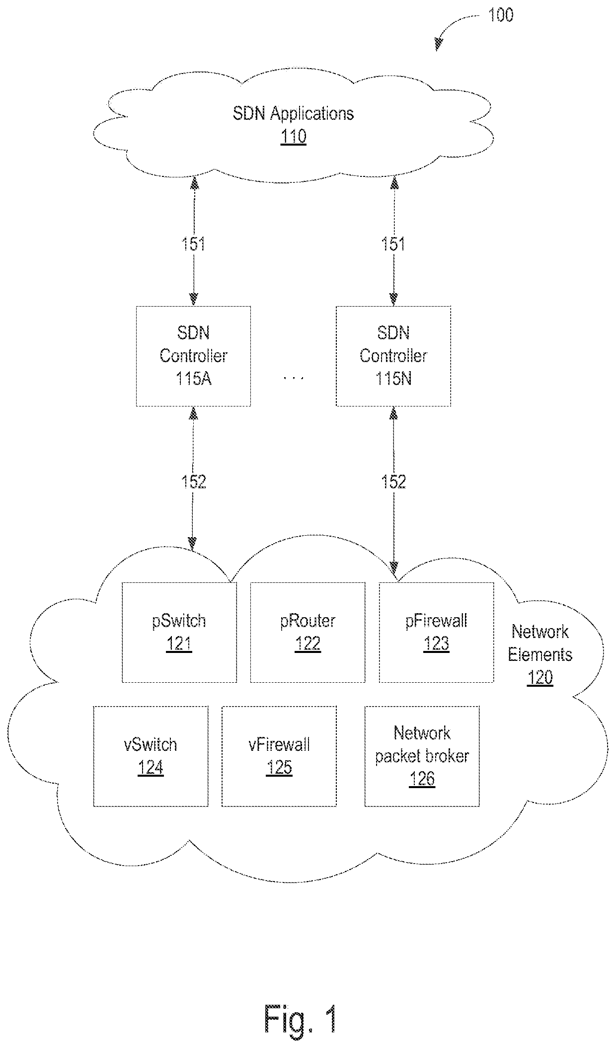
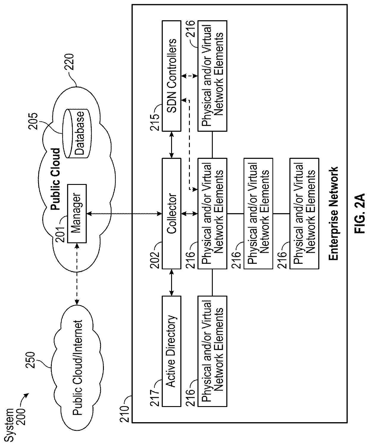
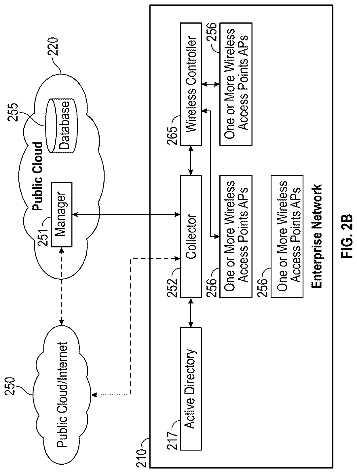
The patent describes a system for automatically controlling a network using a dynamic control loop. The system includes collectors that receive network traffic data from multiple networks and enterprise systems, and a remote network manager that analyzes the data and sends control policies to the collectors. The system can extract features from the data, measure the effectiveness of the control policies, and learn patterns from the data to improve future control policies. The system can also index the data and provide cross-network data analysis. Overall, the system enables efficient control of network traffic and improved performance monitoring.

Problems solved by technology

Obtaining business-level insight and control over the applications, users and devices in modern networks is becoming extremely challenging.
However, dedicated hardware has drawbacks in supporting various types of applications and devices deployed in different parts of the network.

Method used


Image

  • System and method for automatic closed loop control
  • System and method for automatic closed loop control
  • System and method for automatic closed loop control

Examples


examples

[0113]FIG. 7 illustrates a diagram of an exemplary SDN enabled network, according to one embodiment. Seven switches s0-s6 and network elements h0-h2 are arranged hierarchically. The top switch s0 is connected to the Internet 750, and a manager 701 is deployed in a server in the public cloud and connected via the Internet 750. A collector 702 is deployed as a virtual machine (VM) on a server attached to switch s6. The switches s0-s6 are SDN enabled switches and a SDN controller 715 is deployed as a server attached to switch s5. An active directory server 725 is also connected to switch s5.

[0114]FIG. 8 illustrates a diagram of an exemplary of legacy network including a SDN-enabled switch, according to one embodiment. Seven switches s0-s6 feed mirrored traffic (as indicated by dotted lines) into a SDN-enabled switch 824. The mirroring configuration is static, and as an example may simply mirror the traffic from each switch's uplink. The collector 802 and SDN controller 815 are deployed...


PUM


Abstract

A system and method for providing automatic closed loop control of a network using a dynamic control loop. The system includes one or more collectors and a remote network manager. The one or more collectors are configured to receive network traffic data from a plurality of network elements in the network. The remote network manager computes an initial control policy to the programmable network elements using (1) high-level policies, security requirements, and any anomalous traffic behavior; (2) configuration capability and current configuration of underlying network elements; (3) network topology, statistics, and tolerable configuration change; and (4) control loop parameters including stability, oscillation, and timescale. The remote network manager sends control policy parameters to the programmable network elements, observes the network, measures effectiveness of the initial control policy with respect to the high-level policy, and computes an updated control policy to send to the programmable network elements.

Description

COPYRIGHT NOTICE[0001]A portion of the disclosure of this patent document contains material that is subject to copyright protection. The copyright owner has no objection to the facsimile reproduction by anyone of the patent document or the patent disclosure, as it appears in the Patent and Trademark Office patent files or records, but otherwise reserves all copyright rights whatsoever.BACKGROUNDTechnical Field[0002]The present disclosure pertains generally to the fields of indexing and controlling networks. More particularly, the present disclosure relates to a system and method for observing and controlling a programmable network via higher layer attributes.Description of the Related Art[0003]Obtaining business-level insight and control over the applications, users and devices in modern networks is becoming extremely challenging. On the applications front, modern networks have a huge mix in application types and deployment locations. For example, a single application might be imple...

Claims


Application Information

Patent Timeline
IPC IPC(8): H04L12/24H04L12/26G06N20/00
CPCH04L41/046H04L43/12H04L41/16H04L43/0829H04L41/147G06N20/00H04L41/0823H04L43/04H04L41/085H04L43/0876H04L41/145H04L41/0816H04L41/0893H04L43/062H04L41/0895H04L41/40H04L43/20H04L41/0894
Inventor SRINIVAS, ANANDBARRY, RICHARDANKUMAH, ABRAHAMKAN, DANIEL
Owner VMWARE INC
Learn More