
Powerboat

Active Publication Date: 2020-02-13
BA TECH LTD
View PDF13 Cites 5 Cited by
  • Summary
  • Abstract
  • Description
  • Claims
  • Application Information

AI Technical Summary

Benefits of technology

The present invention is a powerboat configuration that has low drag at low speeds and can operate efficiently and safely at high speeds. It uses submerged dynamically-adjustable hydrofoils to control the running trim of the boat. The resistance of the present invention is compared to a conventional powerboat and shows that it has lower resistance at low speeds while maintaining comparable resistance figures at higher speeds. The hydrofoils are retractable or movable to protect them when the boat is stationary or underwater. The control system automatically adjusts the hydrofoils to control the running trim of the boat and can also adjust them to control roll and pitch motions or reduce hydrodynamic drag on the hull. The hull is shaped to minimize drag when the boat is operating at lower speeds. The bow has a smooth transition from V-shaped to rounded cross section to combine good performance at planing speeds with efficient performance at non-planing speeds.

Problems solved by technology

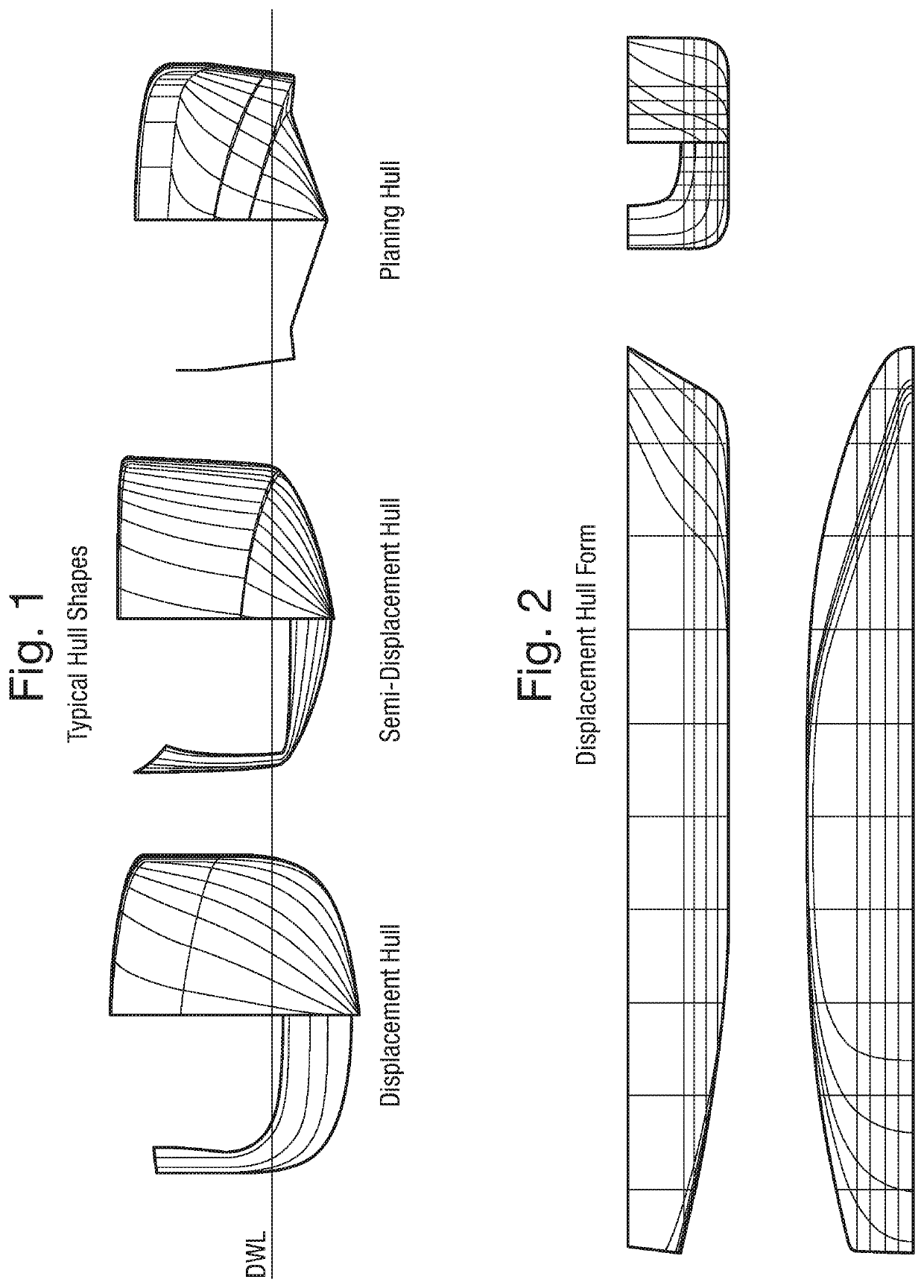
However, hulls of this shape are not suitable for boats which operate at higher speed (i.e. for the semi-planing and planing regime).
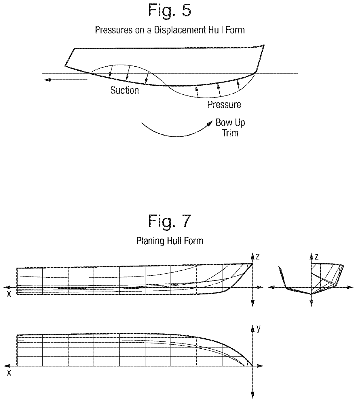
This induces a bow up trim as schematically illustrated in FIG. 5 that results in high drag and this demands unfeasibly high engine power to make the transition to planing speed.
Also, at higher speed, the highly curved hull form induces a lack of stability and controllability, which adversely affects steering control, comfort, and safety.
However, it may spend most of its life operating at lower, more comfortable, and fuel efficient cruising speeds.
Hulls which are designed as above for planing operation have the disadvantage that they have significantly higher drag at low speed, because of the extra volume towards the stern.
The resulting increased wetted area and immersed transom result in higher hydrodynamic drag.
Thus the design constraints arising from a boat's maximum speed may adversely affect its ability to be fuel efficient when the helmsman chooses to operate away from its maximum speed.
It is unsuitable for, and not intended for, hulls operating at higher Froude numbers, being primarily intended for increasing the cruising efficiency of large power superyachts operating in displacement mode.

Method used


Image

  • Powerboat
  • Powerboat
  • Powerboat

Examples


Embodiment Construction

[0048]A powerboat 1 according to the present invention will now be described with reference to FIGS. 10-18.

[0049]As shown in FIGS. 10 and 11, the powerboat 1 of a first embodiment of the invention comprises a hull 2, a plurality of dynamically adjustable hydrofoils 3 positioned towards the rear of the hull 2, below the design waterline, and a control system 14 for the hydrofoils.

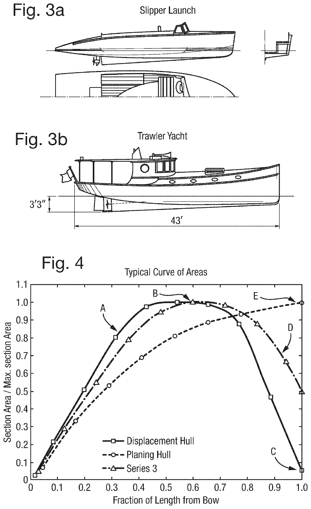
[0050]The hull 2 is shaped similarly to hulls typically used for operation in a displacement mode. The cross sectional area of the hull 2 reduces from the midship point to the transom (i.e. to the stern), such that the immersed area of the transom at rest is less than 40%, preferably less than 30%, more preferably less than 20%, and most preferably less than 10% of the maximum hull cross sectional area. In other words, the immersed volume of the hull 2 reduces from the midship section to the rear of the hull 2. This form of section distribution gives rise to a curve of areas (line A in FIG. 4) that correspon...


PUM


Abstract

A powerboat comprising a hull, a plurality of dynamically adjustable hydrofoils positioned below the waterline towards the rear of the hull, and a control system, wherein the cross sectional area of the hull below the waterline decreases towards the rear of the hull, and the control system is configured to adjust the hydrofoils in operation of the powerboat to control the running trim of the powerboat. The powerboat can operate efficiently at over a wide range of Froude numbers, in particular both low (displacement mode) speeds and high (planing mode) speeds.

Description

CROSS-REFERENCE TO RELATED APPLICATIONS[0001]This application is a 371 of PCT Application No. PCT / GB2018 / 050405 filed on Feb. 15, 2018, which claims the benefit of British Patent Application No. 1702625.3 filed on Feb. 17, 2017, the contents of which are incorporated herein by reference in their entirety.FIELD OF INVENTION[0002]The present invention relates to a powerboat, which is optimized to operate with minimum hydrodynamic resistance at a wide range of speeds.BACKGROUND OF THE INVENTION[0003]A wide range of hull shapes for powerboats are known, and the shape of the hull varies in accordance with the speed at which the powerboat is intended to operate. The speed of a boat is commonly characterized by the Speed / Length ratio or the Froude number, a nondimensional number which is defined as: Fn=V√{square root over (gL)}, where V is the speed, g is the gravitational constant (9.81 m / s2 if using SI units), and L is the waterline length. Traditionally conventional powerboat hull types...

Claims


Application Information

Patent Timeline
IPC IPC(8): B63B1/28B63B1/30
CPCB63B1/30B63B1/286B63B34/05
Inventor CLAUGHTON, ANDREW RONALDSCHOFIELD, SIMON
Owner BA TECH LTD
Learn More