Low power solenoid with dropout detection and auto re-energization

a low-power solenoid and auto-re-energization technology, applied in the field of low-power control systems, can solve problems such as increased energy, and achieve the effect of maintaining a level of energy and reducing the level of energy

Active Publication Date: 2020-02-20
AUTOMATIC SWITCH
View PDF0 Cites 0 Cited by
  • Summary
  • Abstract
  • Description
  • Claims
  • Application Information

AI Technical Summary

Benefits of technology

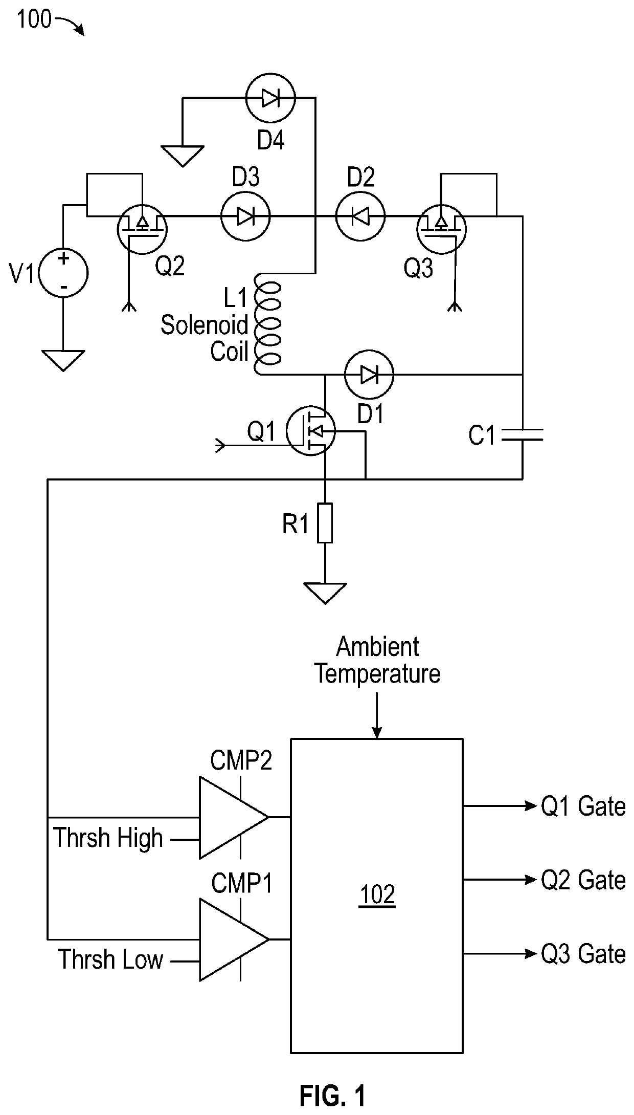
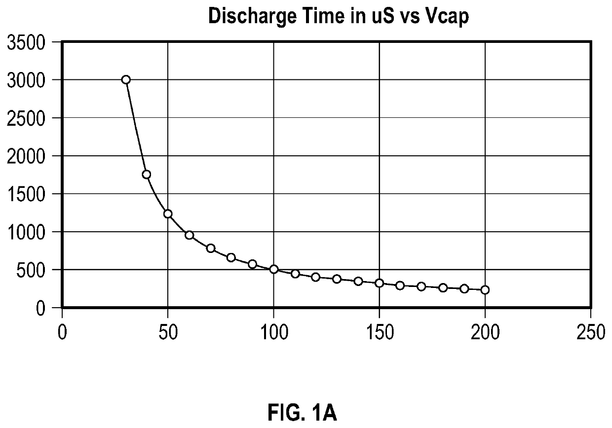
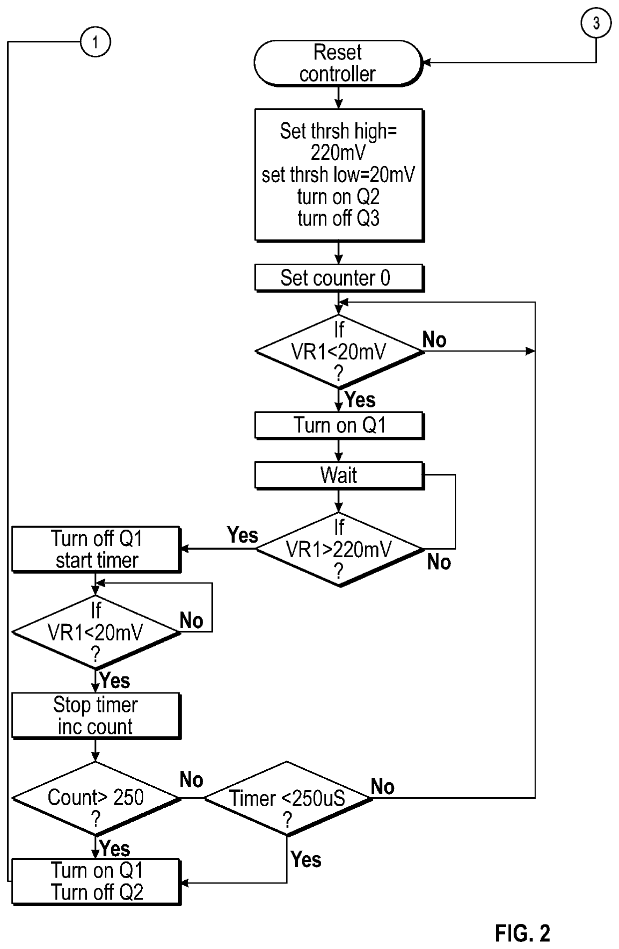
[0016]A method can include pulsing a discharge switch and maintaining a level of energy in an energy storage device sufficient to cause the inductor to produce an actuating magnetic field. A method can include maintaining a level of energy in an energy storage device sufficient to cause an inductor to produce an actuating magnetic field within 100 milliseconds or another period of time of a dropout condition of the inductor being detected. A method can include driving a discharge switch, such as by way of pulse width modulation, for a number of pulses adequate to maintain a level of energy in an energy storage device sufficient to cause an inductor coupled to the energy storage device to produce an actuating magnetic field upon or following a dropout condition of the inductor being detected. A method can include closing a discharge switch for a time period adequate to allow measurement of inductance without reducing the level of energy in an energy storage device below a level sufficient to cause an associated inductor to produce an actuating magnetic field.

Problems solved by technology

One issue with both types of devices is that the increased energy only occurs on initial powerup of the device, and any change in state of the device after that time is not detected or acted upon.

Method used


Image

  • Low power solenoid with dropout detection and auto re-energization
  • Low power solenoid with dropout detection and auto re-energization
  • Low power solenoid with dropout detection and auto re-energization

Examples


Embodiment Construction

[0026]The Figures described above and the written description of specific structures and functions below are not presented to limit the scope of what Applicant has invented or the scope of the appended claims. Rather, the Figures and written description are provided to teach any person skilled in the art to make and use the invention(s) for which patent protection is sought. Those skilled in the art will appreciate that not all features of a commercial embodiment of the disclosure are described or shown for the sake of clarity and understanding. Persons of skill in this art will also appreciate that the development of an actual commercial embodiment incorporating aspects of the present disclosure can require numerous implementation-specific decisions to achieve the developer's ultimate goal for the commercial embodiment(s). Such implementation-specific decisions may include, and likely are not limited to, compliance with system-related, business-related, government-related and other...


PUM

PropertyMeasurementUnit
voltage VR1aaaaaaaaaa
peak currentaaaaaaaaaa
voltagesaaaaaaaaaa

Abstract

A solenoid control circuit can make measurements during operation to determine the state of a solenoid and can provide for rapid re-energization of a solenoid upon detection of a dropout condition. A method of controlling a solenoid can include closing an input switch, cycling a low side switch based on voltage drop across a resistor, opening the input switch after a time interval, closing the low side switch and driving a discharge switch to control the discharge current rate from an energy storage device to an inductor. The method can include determining a condition of the inductor based on a time interval between actuation of comparators and maintaining a level of energy in the energy storage device sufficient to cause the inductor to produce a magnetic field for actuating a valve.

Description

CROSS REFERENCE TO RELATED APPLICATIONS[0001]Not applicable.STATEMENT REGARDING FEDERALLY SPONSORED RESEARCH OR DEVELOPMENT[0002]Not applicable.REFERENCE TO APPENDIX[0003]Not applicable.BACKGROUND OF THE INVENTION[0004]Field of the Invention The inventions disclosed and taught herein relate generally to control systems; and more specifically relate to low power control systems.DESCRIPTION OF THE RELATED ART[0005]U.S. Pat. No. 5,532,526 teaches “[a] control circuit for supplying a load with current having a high-amplitude portion with a rapid leading edge, and a lower-amplitude portion. The circuit is input-connected to a low-voltage supply source, and comprises a number of actuator circuits parallel-connected between the input terminals and each including a capacitor and a load. Each actuator circuit also comprises a first controlled switch between the respective load and a reference line, for enabling energy supply and storage by the respective load. A second controlled switch is p...

Claims


Application Information

Patent Timeline
Patent Type & Authority Applications(United States)
IPC IPC(8): H01F7/18H02M3/155H01H47/04
CPCH02M3/155H01F7/1816H01H47/043H01F2007/1822H02M3/1555
Inventor HALLER, JOHN J.
Owner AUTOMATIC SWITCH
Why Eureka
Try Eureka