Bandgap engineered charge trapping memory in two-transistor nor architecture

a technology of charge trapping memory and bandgap, which is applied in the field of flash memory technology, can solve the problems of limiting the ability to increase the density of flash memory, affecting the performance of flash memory, so as to reduce power consumption and improve performance. the effect of programming

Active Publication Date: 2014-10-14
MACRONIX INT CO LTD
View PDF88 Cites 13 Cited by
  • Summary
  • Abstract
  • Description
  • Claims
  • Application Information

AI Technical Summary

Benefits of technology

[0015]An integrated circuit device, based on this architecture comprises a memory array with plural bit lines coupled with corresponding columns of memory cells in the array, plural reference lines, a plurality of access gate word lines coupled to access gates in corresponding rows in the array and a plurality of memory gate word lines coupled to memory gates in corresponding rows in the array. The memory cells in the array include respective access transistors having access gates and memory transistors having memory gates arranged in series between the corresponding bit lines and one of the plural reference lines. A memory transistor in a memory cell comprises a semiconductor body including a channel having a channel surface and a charge storing dielectric stack between the memory gate and the channel surface. The dielectric stack comprises a bandgap engineered, tunneling dielectric layer contacting one of the gate (for gate injection tunneling) and the channel surface (for channel injection tunneling). The bandgap engineered, tunneling dielectric layer includes a combination of materials arranged to establish a relatively low valence band energy level near said one of the gate and the channel surface, and an increase in valence band energy level at a first distance from said one of the gate and the channel surface and a decrease in valence band energy at a second distance more than 2 nm from said one of the gate and the channel surface. The dielectric stack of the memory cell also includes a charge trapping dielectric layer between the tunneling dielectric layer having a thickness greater than 5 nm and a blocking dielectric layer between the charge trapping layer and another of the gate and the channel surface. Control circuitry on the integrated circuit includes logic for reading, programming and erasing data stored in the memory cells in the array, taking advantage of the unique characteristics of the 2T NOR memory cell having a BE-SONOS structure, including the characteristic that the tunneling dielectric layer effectively blocks tunneling at relatively low electric fields encountered during operation of the device during read operations, and as an unselected cell during programming and erase, while enabling efficient programming and erase of selected cells or selected sectors, at moderate electric fields.
[0016]The 2T NOR architecture enables fast read operations, where parallel connection of the memory cells, and the fact that memory transistor in the memory cells has a terminal in the semiconductor body, with a conductive contact directly connecting the terminal and a bit line, provide for relatively high currents at low operating voltages.
[0017]The use of BE-SONOS structures enables memory cells in which the access transistor and the memory transistor both, have the same dielectric stack, including the tunneling dielectric layer, to allow for ease of manufacturing and dense layouts of the array. The ability of the BE-SONOS structure to block tunneling at low electric fields allows the access transistor to operate as a standard field effect device, without trapping charge during the programming and erasing of memory transistor in the same or adjacent cells.
[0021]In alternatives for both gate injection and channel injection embodiments, the control circuitry is arranged to induce channel hot electron programming. In alternatives of the channel hot electron programming devices, the access transistor can be biased to act as a current limiting device, improving performance and reducing power consumption during programming in this manner.
[0022]The large operating window possible using BE-SONOS structures enables embodiments storing multiple bits per cell.

Problems solved by technology

As the density increases in memory devices, and the floating gate memory cells get closer and closer together, interference between the charge stored in adjacent floating gates becomes a problem.
This is limiting the ability to increase the density of flash memory based on floating gate memory cells.
However at that thickness, the endurance and charge retention characteristics of the memory cell are poor relative to traditional floating gate technology.
Also, with relatively thick tunneling dielectric layers, the electric field required for the erase operation also causes electron injection from the gate through the blocking dielectric layer.
However, if the erase saturation level is too high, the cell cannot be erased at all, or the threshold margin between the programmed and erased states becomes too small for many applications.
However, any leakage current from the cells along a given bit line can interfere with the ability to successfully read the data.
Problems associated with the use of floating gate memory devices, including the need to use, and associated costs of, two separate polysilicon deposition steps.
Also, problems arise as the size of the devices shrinks with interference between adjacent cells.
These issues have prevented its widespread use for embedded memory on large system-on-a-chip, high density devices.
The Shimoji et al. cell, because of its low voltage operation during programming and erasing, is likely to suffer problems with disturbance of the charge stored in the memory transistor even at low voltages used for driving the access transistors.

Method used


Image

  • Bandgap engineered charge trapping memory in two-transistor nor architecture
  • Bandgap engineered charge trapping memory in two-transistor nor architecture
  • Bandgap engineered charge trapping memory in two-transistor nor architecture

Examples


Embodiment Construction

[0059]A detailed description of embodiments of the present invention is provided with reference to the FIGS. 3-45.

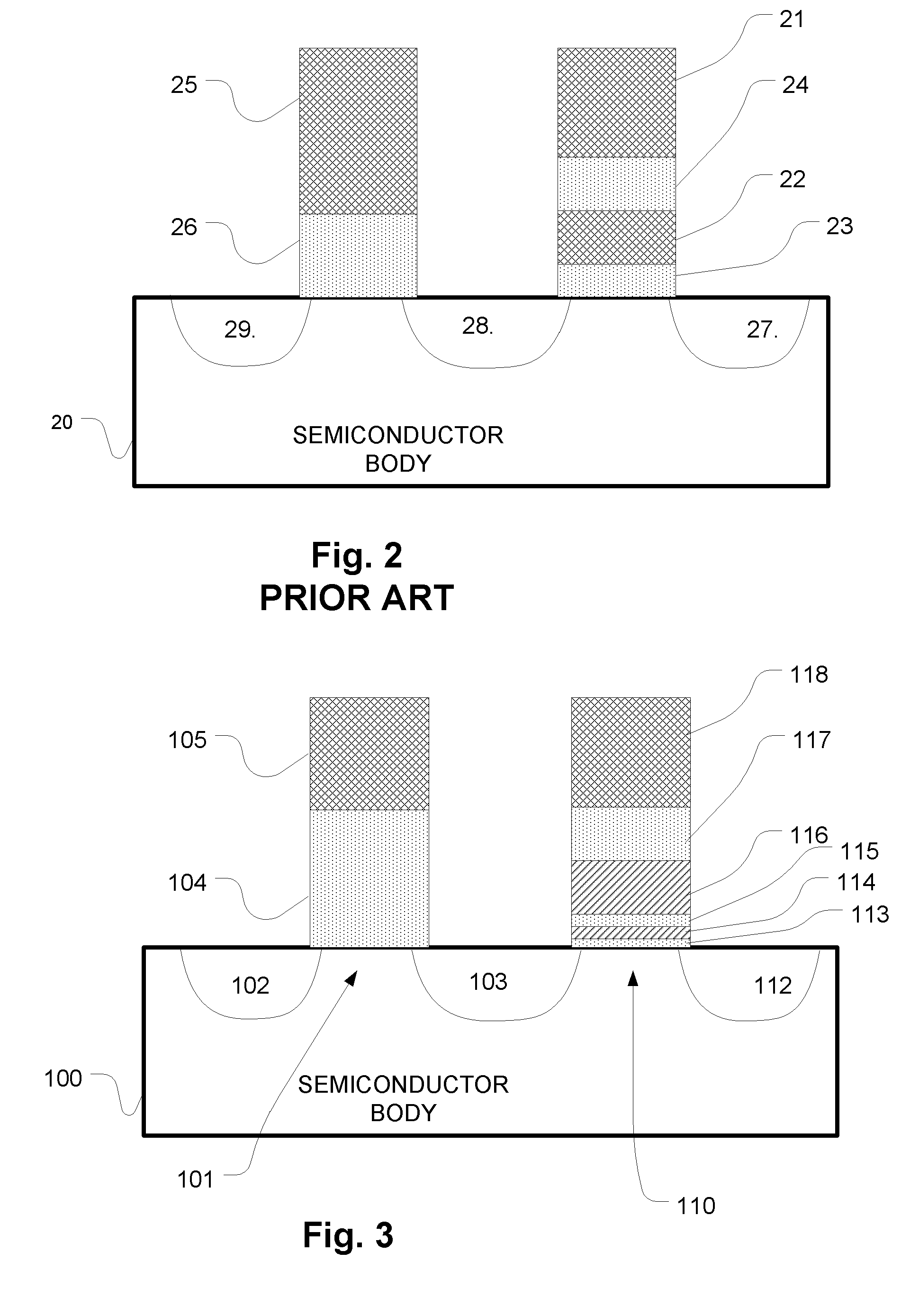
[0060]FIG. 3 is a simplified diagram of a 2T cell including charge trapping memory transistors employing a bandgap engineered dielectric tunneling layer. The memory cell is formed on a semiconductor body 100, and includes an access transistor and memory transistor. The access transistor includes a channel 101, a source 102 and a drain in terminal 103. A gate dielectric layer 104 overlies the channel 101, and a gate 105 overlies the gate dielectric 104. The memory transistor includes a channel 110, a source in terminal 103 and a drain 112 adjacent the channel. A gate 118 overlies a multilayer stack of dielectric materials acting as the charge storage structure, including a blocking dielectric layer, a charge trapping layer and a tunneling layer. In this example, the charge trapping layer is in contact with the tunneling layer, but can be otherwise disposed between the tun...


PUM


Abstract

A 2T cell NOR architecture based on the use of BE-SONOS for embedded memory includes memory cells having respective access transistors having access gates and memory transistors having memory gates arranged in series between the corresponding bit lines and one of the plural reference lines. A memory transistor in a memory cell comprises a semiconductor body including a channel having a channel surface and a charge storing dielectric stack between the memory gate and the channel surface. The dielectric stack comprises a bandgap engineered, tunneling dielectric layer contacting one of the gate (for gate injection tunneling) and the channel surface (for channel injection tunneling). The dielectric stack of the memory cell also includes a charge trapping dielectric layer on the tunneling dielectric layer and a blocking dielectric layer.

Description

BACKGROUND OF THE INVENTION[0001]1. Field of the Invention[0002]The present invention relates to flash memory technology, and more particularly to charge trapping memory technology adaptable for high speed erase and program operations and suitable for use as embedded memory in large scale integrated circuits.[0003]2. Description of Related Art[0004]Flash memory is a class of non-volatile integrated circuit memory technology. Traditional flash memory employs floating gate memory cells. As the density increases in memory devices, and the floating gate memory cells get closer and closer together, interference between the charge stored in adjacent floating gates becomes a problem. This is limiting the ability to increase the density of flash memory based on floating gate memory cells. Another type of memory cell used for flash memory can be referred to as a charge trapping memory cell, which uses a dielectric charge trapping layer in place of the floating gate. Charge trapping memory ce...

Claims


Application Information

Patent Timeline
Patent Type & Authority Patents(United States)
IPC IPC(8): G11C16/04H01L21/28H01L27/115H01L29/423H01L29/51
CPCH01L21/28282H01L29/4234H01L27/11565G11C16/0433H01L27/11568H01L29/513H01L29/40117H10B43/10H10B43/30
Inventor LUE, HANG-TING
Owner MACRONIX INT CO LTD
Why Eureka
Try Eureka