
Disinfecting device having a power supply and a fluid outlet

a technology of liquid outlet and disinfecting device, which is applied in the direction of water treatment location, water treatment parameter control, waste water treatment from bathing facilities, etc., can solve the problems of inconvenient disinfection device, inability to improve water quality, and large safety risks, and achieve reliable disinfection and simple liquid disinfection

Active Publication Date: 2013-04-16
KSB AG
View PDF34 Cites 13 Cited by
  • Summary
  • Abstract
  • Description
  • Claims
  • Application Information

AI Technical Summary

Benefits of technology

The invention provides a simple liquid disinfecting device that ensures reliable disinfection. It uses an irradiator that has a good disinfection action with low energy consumption. The device can be used to disinfect liquids that flow out of an outlet, such as water, for the first time. The device can kill bacteria, viruses, yeasts, fungi, and other harmful microorganisms. It is suitable for use in water conduction systems and can easily determine its performance based on the pressure values of the system.

Problems solved by technology

A disadvantage is that electrical connection wires lead directly away from the nozzle, this presenting a considerable safety risk.
This device, which is designed for a high-volume beverage machine, attempts to maintain an existing water quality, but the water quality cannot be improved.
The device is not suitable for disinfection, that is to saying killing existing bacteria, in particular Legionella, and / or rendering such bacteria harmless.
One disadvantage, besides the high structural complexity and the large space requirement, is the additional external control unit to which the UV lamp has to be connected.

Method used


Image

  • Disinfecting device having a power supply and a fluid outlet
  • Disinfecting device having a power supply and a fluid outlet
  • Disinfecting device having a power supply and a fluid outlet

Examples


Embodiment Construction

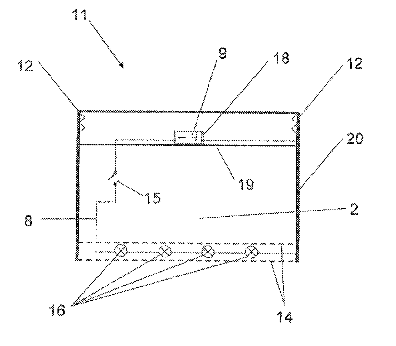
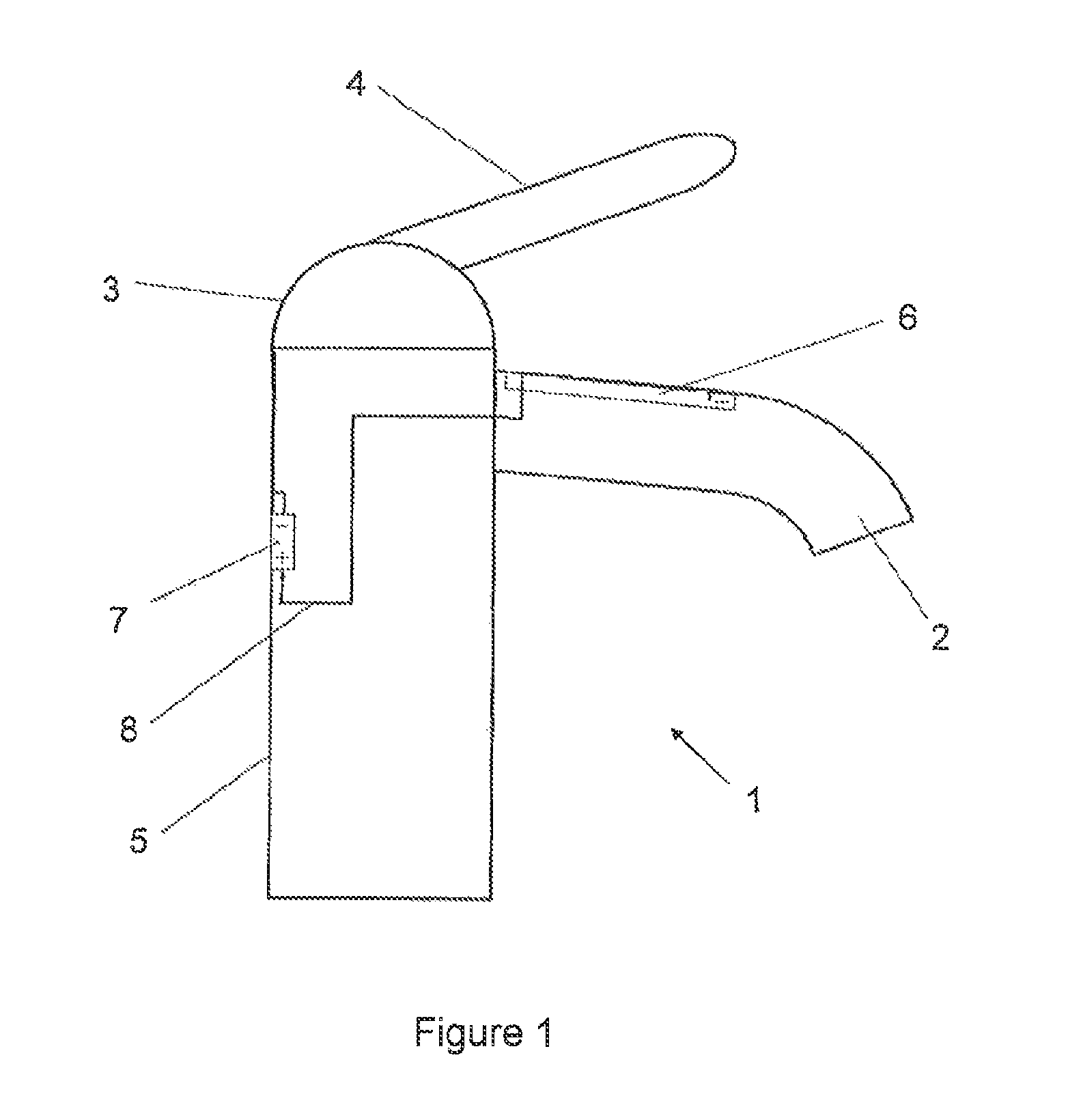
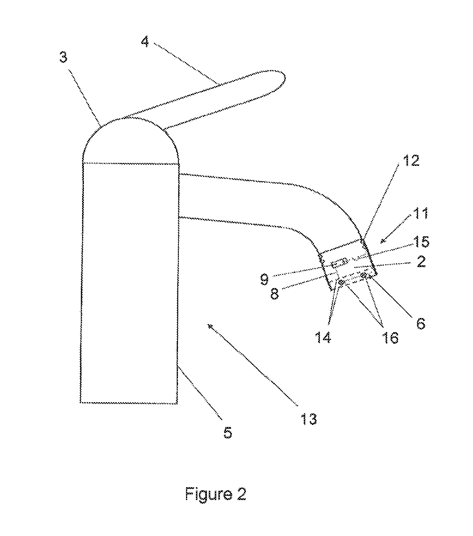
[0037]FIG. 1 shows a schematic illustration of a device according to the invention in the form of a sanitary fitting 1 having an outlet 2, a fitting head 3 with a lever 4 and a fitting base 5. In the device 1, an irradiator 6 is integrated in the outlet 2 for irradiating a liquid which is located in the outlet 2 and / or which flows through the outlet with UV light. An electrical supply 7, for example a battery, is integrated in the fitting base 5. The electrical supply 7 is arranged in a replaceable manner at the edge of the fitting base 5. The electrical supply 7 supplies the irradiator 6 with a voltage in the low-voltage range, a so-called low voltage, via an electrical line 8.

[0038]The electrical circuit is closed by the fitting head. The irradiator 6 has one or more UV-C radiation sources—not illustrated individually here—for irradiating a liquid which flows out through the outlet 2. The irradiator 6 has a good disinfection action together with a low level of energy consumption. ...


PUM

PropertyMeasurementUnit
voltageaaaaaaaaaa
voltageaaaaaaaaaa
power consumptionaaaaaaaaaa

Abstract

A disinfecting device having an outlet (2, 42) for a flowing liquid, particularly water, and a UV irradiator (6), preferably a UV-C radiator (16) or one or more UV-C emitting light emitting diodes, and an electric power supply (7), such as a battery, turbine driven generator or a solar module, for supplying the UV irradiator with up to 25 V alternating voltage or up to 60 V direct voltage. The outlet may be constructed with a reflective interior, and a controller for regulating liquid temperature, liquid pressure and / or liquid flow rate and / or an aerator (14) for introducing air into the flowing liquid may be integrated into the device, which may be a plumbing fixture such as a water spigot.

Description

CROSS REFERENCE TO RELATED APPLICATIONS[0001]This application is a continuation of international patent application no. PCT / EP2009 / 006412, filed Sep. 4, 2009, designating the United States of America and published in German on Mar. 18, 2010 as WO 2010 / 028779, the entire disclosure of which is incorporated herein by reference. Priority is claimed based on Federal Republic of Germany patent application no. DE 10 2008 047 069.4, filed Sep. 12, 2008.BACKGROUND OF THE INVENTION[0002]The invention relates to a device having an outlet for a liquid, in particular water, and having a means for irradiating the liquid with UV light, it being possible for the irradiator to be supplied with electrical power and the irradiator being arranged at the outlet or integrated in the outlet.[0003]U.S. Pat. No. 4,899,057 (=DE 37 86 219) discloses a device of this kind This device has an element for emitting light beams, with which element a container containing liquid or the mouth of a dispensing line is ...

Claims


Application Information

Patent Timeline
Patent Type & Authority Patents(United States)
IPC IPC(8): C02F1/32A61L2/10
CPCC02F1/325C02F2103/002C02F2103/42C02F2201/009C02F2201/3222C02F2209/02C02F2209/03C02F2209/40C02F2209/44C02F2307/06E03C2201/40Y02W10/37Y02A20/212
Inventor DORNSEIFER, FRIEDER
Owner KSB AG
Learn More