Atherectomy catheter

a catheter and atherectomy technology, applied in the field of atherectomy catheters, can solve the problems of reducing affecting the blood circulation to the arms, legs, stomach and kidneys, and affecting the ability of the device to work normally, so as to reduce the chance of the device moving and effectively cut the diseased tissue

Active Publication Date: 2020-02-27
AVINGER
View PDF0 Cites 19 Cited by
  • Summary
  • Abstract
  • Description
  • Claims
  • Application Information

AI Technical Summary

Benefits of technology

[0022]In particular, described herein are atherectomy catheters devices described including one or more cutters configured to cut tissue that are actuated by longitudinal motion of a drive shaft, e.g., in the proximal / distal axis of the device. The same drive shaft may be used to rotate the cutter, which may be a ring-type cutter at a rotational speed appropriate for cutting the tissue. For example, the cutter may rotate at between about 200 and 5000 RPM (e.g., about 500 RPM, about 600 rpm, about 700 RPM, about 1000 RPM, etc.). Any of these variations may also include imaging such as optical coherence tomography (OCT) imaging configured to image the vessels tissue, including penetrating some depth into the vessel to image the tissue surrounding the blood vessel (such as the intima, media and externa layers). Imaging may help navigate as well as remove atheromatous plaques.
[0026]Force limiting controls may also be used to ensure the input forces do not exceed what is required to effectively cut diseased tissue. This may reduce the chances of the device moving outside the perimeter of the lesion while activated thereby cutting into healthy arterial wall.

Problems solved by technology

PAD is a silent, dangerous disease that can have catastrophic consequences when left untreated.
Over time, this substance hardens and thickens, which may interfere with blood circulation to the arms, legs, stomach and kidneys.
Blood circulation to the brain and heart may be reduced by CTOs, increasing the risk for stroke and heart disease.
Traditional atherectomy devices have been plagued by a number of problems that have severely limited market adoption of these devices.
Additional reasons for the lack of adoption are the cost, complexity and limited applicability of currently available devices.
Many designs are unable to treat the wide range of disease states present in long complex lesions; luminal gain is often limited by the requirement of the physician to introduce multiple devices with increased crossing profiles; tissue collection is either unpredictable or considered unnecessary based on assumptions regarding small particle size and volumes; and optimal debulking is either not possible due to lack of intravascular visualization or requires very long procedure times. Based on these limitations current devices are likely to perform poorly in the coronary vasculature where safety and efficacy in de novo lesions, ostials, and bifurcations continue to pose great challenges.
The reliability of these devices to produce clinically insignificant embolization has been questioned when not aspirated through the catheter to an external reservoir.
In early clinical evaluations of aspiration the presence of negative pressure at the distal working assembly cause the artery to collapse around the cutting element causing more aggressive treatment, dissections and / or perforations.
In addition, the option for post procedural analysis of any removed disease is extremely limited or impossible.
These large distal tip assemblies can limit the capabilities of the system to access small lesions and create additional trauma to the vessel.
Currently available atherectomy devices also do not include, and are poorly adapted for use with, real time image guidance.
Disposable drive systems, however, are expensive and impractical.
On the other hand, reusable drive systems can be problematic for keeping the surgical field sterile.
Unfortunately, placement of the guidewire, while critical for effective treatment, may be difficult.
In particular, when placing a guidewire across an occlusion, it may be difficult to pass the guidewire through the occlusion while avoiding damage to the artery.
For example, it is often difficult to prevent the guidewire from traveling out of the true lumen and into the subintimal layers, such as the adventitia and surrounding tissues.
This can cause damage to the vessel and, once out of the true lumen, it can be difficult to direct the guidewire back into the true lumen, thereby preventing effective treatment of the occlusion.

Method used


Image

  • Atherectomy catheter
  • Atherectomy catheter
  • Atherectomy catheter

Examples


examples

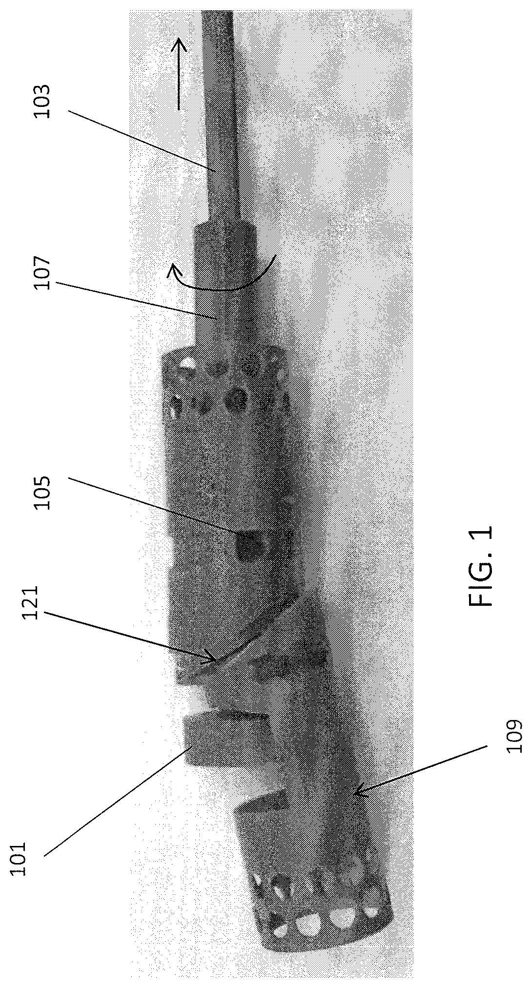
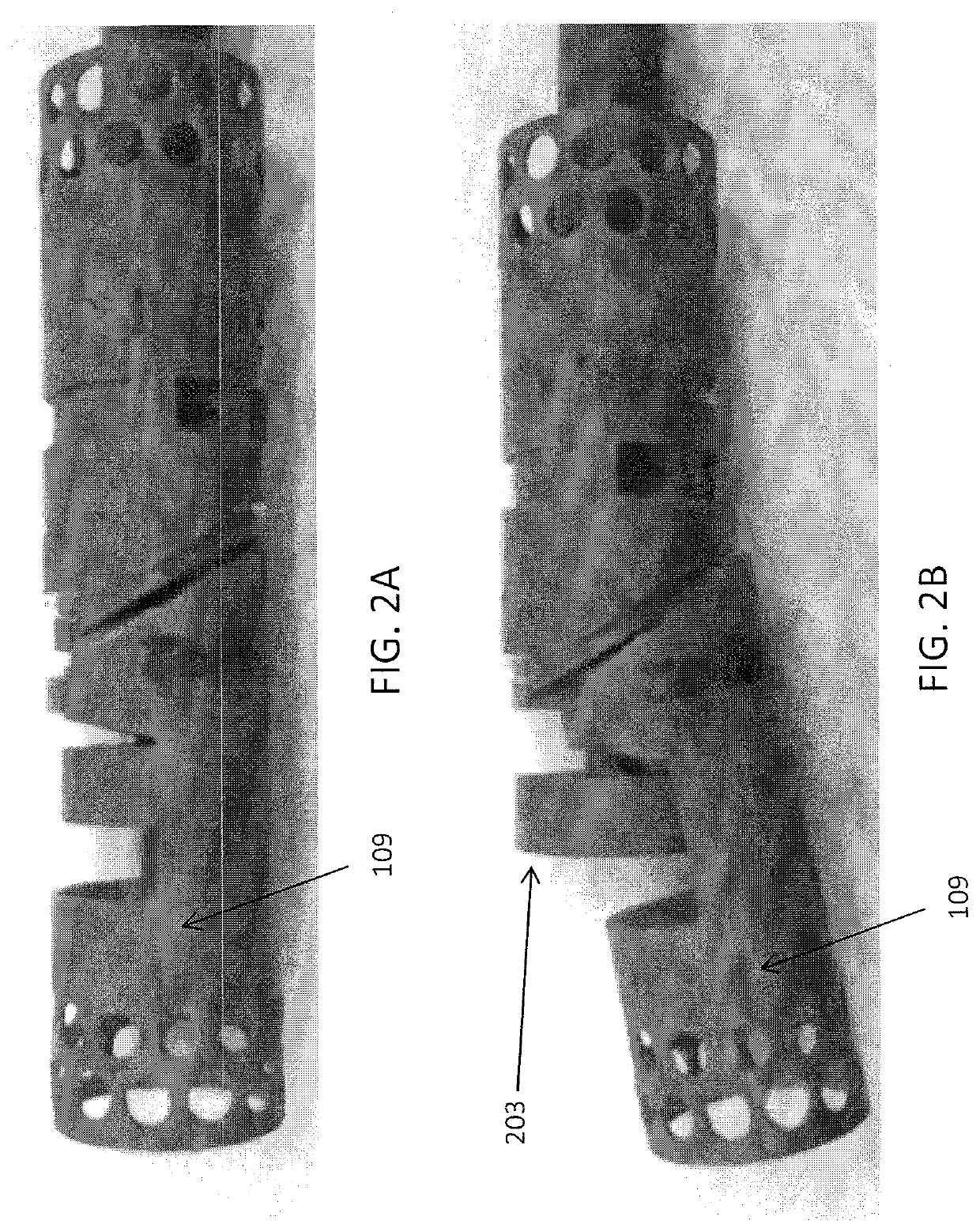
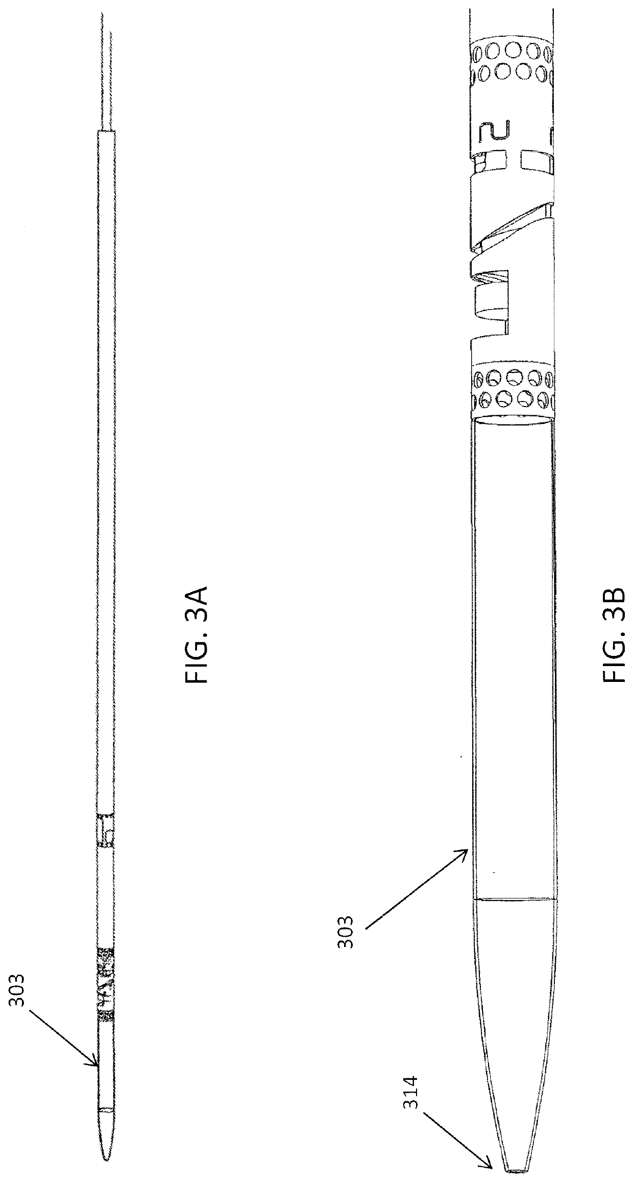
[0152]FIGS. 3A and 3B show one variation of an atherectomy catheter that includes both a rotating cutter and a rotating imaging sensor. In this variation the cutter and imaging sensor may be rotated separately, and the distal tip region may be displaced to expose the cutting edge of the cutter, allowing material to be removed. OCT images may be collected continuously (in a 360 degree view) before, during, or after cutting. In this variation the cutter is positioned distally to the imaging sensor. The distal tip region may be displaced by applying pulling (or in some variations pushing) force to the drive shaft of the cutter, which displaces the distal tip region. Moving the drive shaft laterally (e.g., proximally or distally) to displace the distal tip does not otherwise effect the operation of the cutter, which may continue to rotate. This may allow the distal tip region to help control the thickness of slices cut from the tissue by controlling the amount that the cutting edge is e...


PUM


Abstract

Described herein are atherectomy catheters, systems and methods that include longitudinally displaceable drive shafts that drive actuation of one or more cutters at the distal end of the catheter. The catheters described herein may include one or more imaging sensors for imaging before, during or after cutting tissue. In some variations the imaging sensor may be rotated around the perimeter of the catheter independently of the rotation of the cutter. Also describe herein are imaging catheters that may be used without cutters.

Description

CROSS REFERENCE TO RELATED APPLICATIONS[0001]This patent application is a continuation in part of U.S. patent application Ser. No. 15 / 162,330, filed May 23, 2016, titled “ATHERECTOMY CATHETERS WITH LONGITUDINALLY DISPLACEABLE DRIVE SHAFTS,” which is a continuation of U.S. patent application Ser. No. 13 / 175,232, filed Jul. 1, 2011, titled “ATHERECTOMY CATHETERS WITH LONGITUDINALLY DISPLACEABLE DRIVE SHAFTS,” now U.S. Pat. No. 9,345,510, which claims priority to U.S. Provisional Patent Application No. 61 / 360,886, titled “ATHERECTOMY CATHETERS WITH LONGITUDINALLY DISPLACEABLE DRIVE SHAFT,” filed on Jul. 1, 2010, U.S. Provisional Patent Application No. 61 / 468,396, titled “OCCLUSION CROSSING DEVICES, IMAGING, AND ATHERECTOMY DEVICES,” filed on March 28, 2011, and U.S. Provisional Patent Application No. 61 / 492,693, titled “ATHERECTOMY CATHETERS WITH LONGITUDINALLY DISPLACEABLE DRIVE SHAFTS” and filed on Jun. 2, 2011, each of which is incorporated by reference herein in its entirety.[0002]...

Claims


Application Information

Patent Timeline
Patent Type & Authority Applications(United States)
IPC IPC(8): A61B17/3207A61B1/00A61B1/313
CPCA61B1/00183A61B17/320725A61B2090/3735A61B2017/320791A61B17/320783A61B1/3137A61B1/00179A61B90/37A61B2090/3614A61B2017/00292A61B17/320758A61B5/0066A61B1/00165A61B2017/22039A61B2017/22095A61B5/6852
Inventor PATEL, HIMANSHU N.SIMPSON, JOHN B.MCNALL, CHARLES W.SPENCER, MAEGAN K.ZUNG, MICHAELGUPTA, PRIYANSHUSPINELLI, NICHOLAS J.FABRO, MYRA L.SUCGANG, EDUARDOKETAI, THEODORE W.
Owner AVINGER
Why Eureka
Try Eureka