Handle mounting structure

Active Publication Date: 2020-02-27
HANWIT PRECISION IND LTD
View PDF9 Cites 3 Cited by
  • Summary
  • Abstract
  • Description
  • Claims
  • Application Information

AI Technical Summary

Benefits of technology

The present invention provides a handle mounting structure for electronic products with light, thin, short, and small characteristics. The handle mounting structure includes a handle, a locking mechanism, and a positioning device. The handle has a sliding space with an insert plate and a torsion spring. The locking mechanism includes an insert plate and a torsion spring with a coiled positioning portion. The positioning device includes a flat base and a hook block. The handle can be securely fastened to a sliding box of a cabinet through the locking mechanism and positioning device. The outer cover of the locking mechanism can be easily replaced and the handle can be firmly positioned without vibration. The position-limiting plates are curved to allow for the installation of the outer cover without increasing the thickness of the handle. The two position-limiting plates enhance the structural strength of the handle and facilitate grasping of the user's hand.

Problems solved by technology

However, since the current electronic products are developing toward light, thin, short, and small designs, the cabinet and the internal sliding boxes must be designed to be smaller and smaller.

Method used


Image

  • Handle mounting structure
  • Handle mounting structure
  • Handle mounting structure

Examples


Embodiment Construction

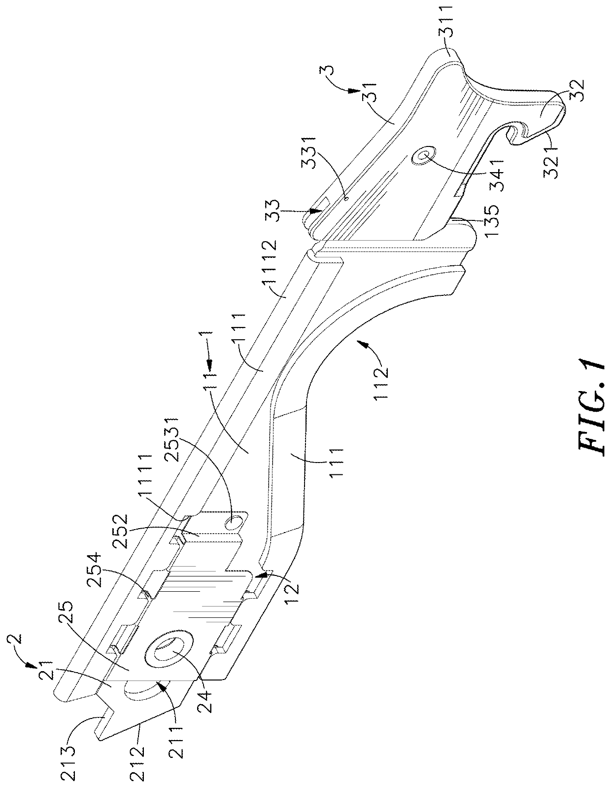
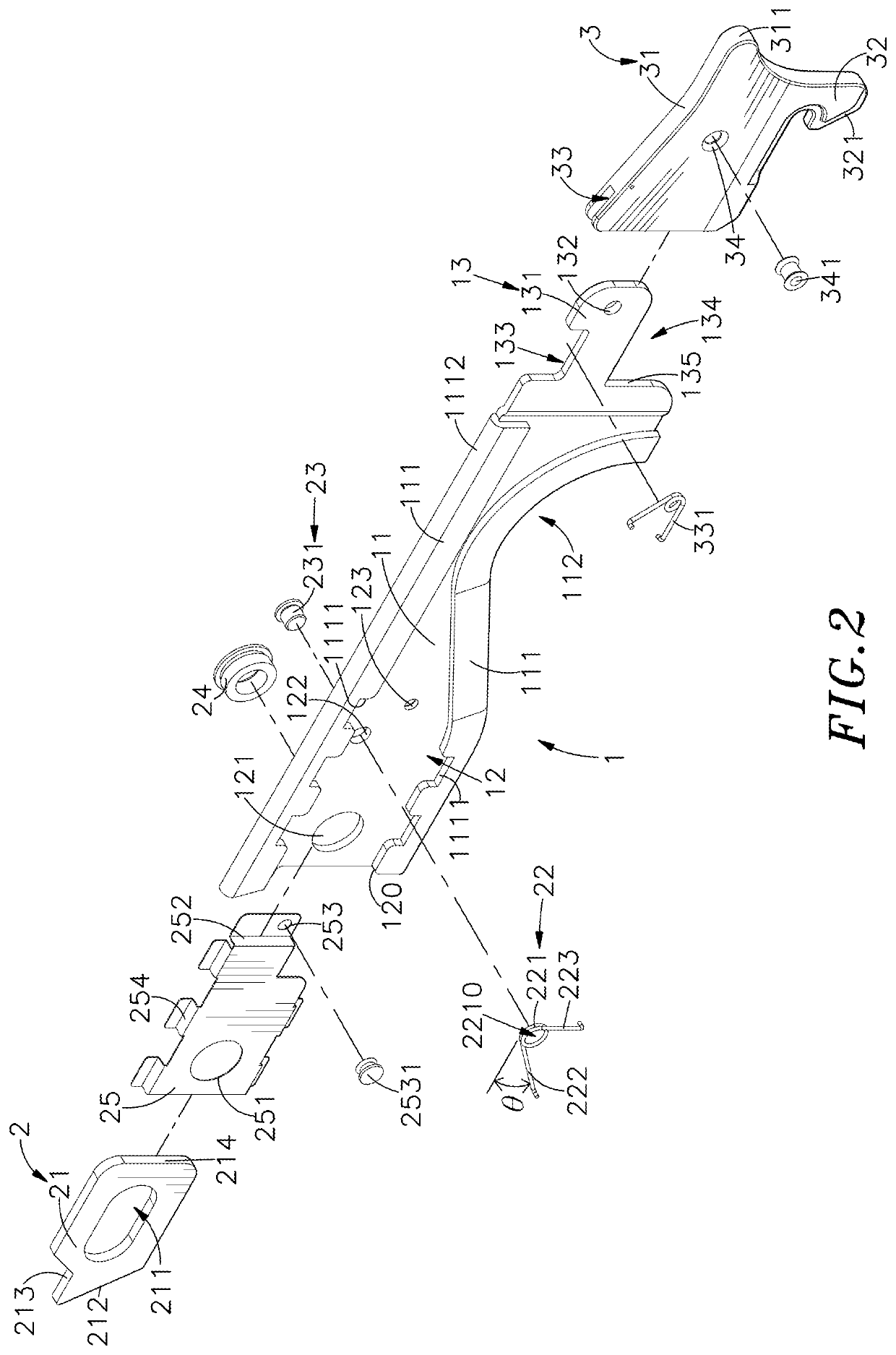
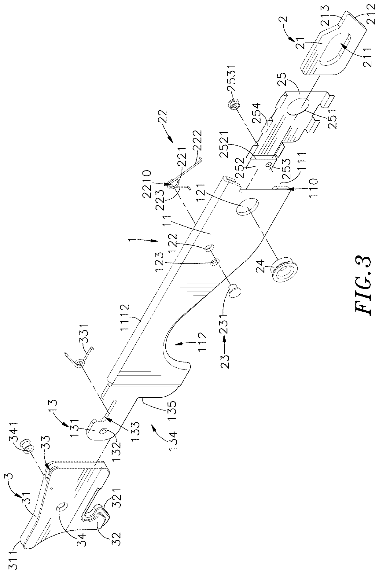
[0019]Referring to FIGS. 1 and 2, a handle mounting structure in accordance with the present invention is shown. The handle mounting structure comprises a handle 1, a locking mechanism 2 and a positioning device 3.

[0020]The handle 1 comprises a handle shaft 11, two position-limiting plates 111 respectively curved from two opposite lateral sides of the handle shaft 11 in direction toward each other with a gap 110 defined between each position-limiting plate 111 and the handle shaft 11, a streamline type grip 112 extended from at least one side of the position-limiting plate 111, a sliding space 12 defined in a side of an opposing internal of the two position-limiting plates 111, an opening 120 defined in a side of the sliding space 12, a mounting hole 121, a locating hole 122 and a positioning hole 123 cut through the sliding space 12, and a mounting unit 13 extended from the handle shaft 11 and disposed at an opposite side of the sliding space 12. The mounting unit 13 comprises a mo...


PUM


Abstract

A handle mounting structure includes a handle including a handle shaft with a sliding space defined in one side thereof and a mounting unit located at one end thereof, a locking mechanism including an insert plate slidably inserted into the sliding space and a torsion spring mounted in the sliding space and stopped between the handle and the insert plate to impart a pressure to the insert plate toward the outside of the sliding space, and a positioning device including a flat base pivotally coupled to the handle and a hook block located at a bottom side of the flat base. The handle can be fastened to a sliding box of a cabinet through locking mechanism and the positioning device, so that the handle is not easily separated from the sliding box, and the sliding box can be surely pulled out of or pushed into the cabinet through the handle.

Description

BACKGROUND OF THE INVENTION1. Field of the Invention[0001]The present invention relates to a handle mounting structure consisting of a handle, a locking mechanism and a positioning device for quick installation in a sliding box of a cabinet, which has a low-profile characteristic.2. Description of the Related Art[0002]With the rapid development of electronic technology, computer technology brings convenience, comfort, speed and other high-efficiency functions to people's life and work, so the application function of electronic technology and computer systems is getting stronger and stronger, the application scope is getting wider and wider. Except personal computers for personal application, industrial computer rooms, building central control systems, central control systems of automated plant operation systems, central processing control systems for video and audio playback, etc., are controlled through centralized management by mounting multiple computer hosts, servers, conversion...

Claims


Application Information

Patent Timeline
IPC IPC(8): B25G3/16B25G3/08B25G1/10H05K5/02
CPCH05K5/0221H05K5/023H05K7/1488B25G1/102B25G3/08B25G3/16H05K7/1489
Inventor WU, MING-DECHANG, CHING-KAI
Owner HANWIT PRECISION IND LTD
Why Eureka
Try Eureka