Barrel valve

Pending Publication Date: 2021-09-02
COLUMBIA INSURANCE CO
View PDF0 Cites 0 Cited by
  • Summary
  • Abstract
  • Description
  • Claims
  • Application Information

AI Technical Summary

Benefits of technology

The present patent is about a fluid metering valve that can be placed between two flow channels in a manifold. The valve has a barrel valve with a passage that runs off-axis through the valve. When the valve is closed, a solid portion of the valve blocks the passage, preventing fluid flow between the two channels. When the valve is opened, a portion of the passage is exposed, allowing a metered amount of fluid flow. The off-axis passage and solid portion of the valve make the manifold thinner and lighter. The valve has a square, rectangular, or rounded rectangular cross-section, which allows for a predictable response to valve manipulation. The valve can change from fully closed to fully open in less than one-hundred twenty degrees of rotation, allowing for a faster rate of fluid flow increase or decrease. The valve also has a minimized volume of material, contributing to weight and size reduction.

Problems solved by technology

Current air distribution manifolds can be large, heavy, and bulky.
Further, precise metering of flow volumes using currently available valves, such as ball valves, is challenging.
Predictable flow volume control is thus a challenge.
While some available valves can provide more precise control over flow volumes, they have their own associated drawbacks.

Method used


Image

  • Barrel valve
  • Barrel valve
  • Barrel valve

Examples


Embodiment Construction

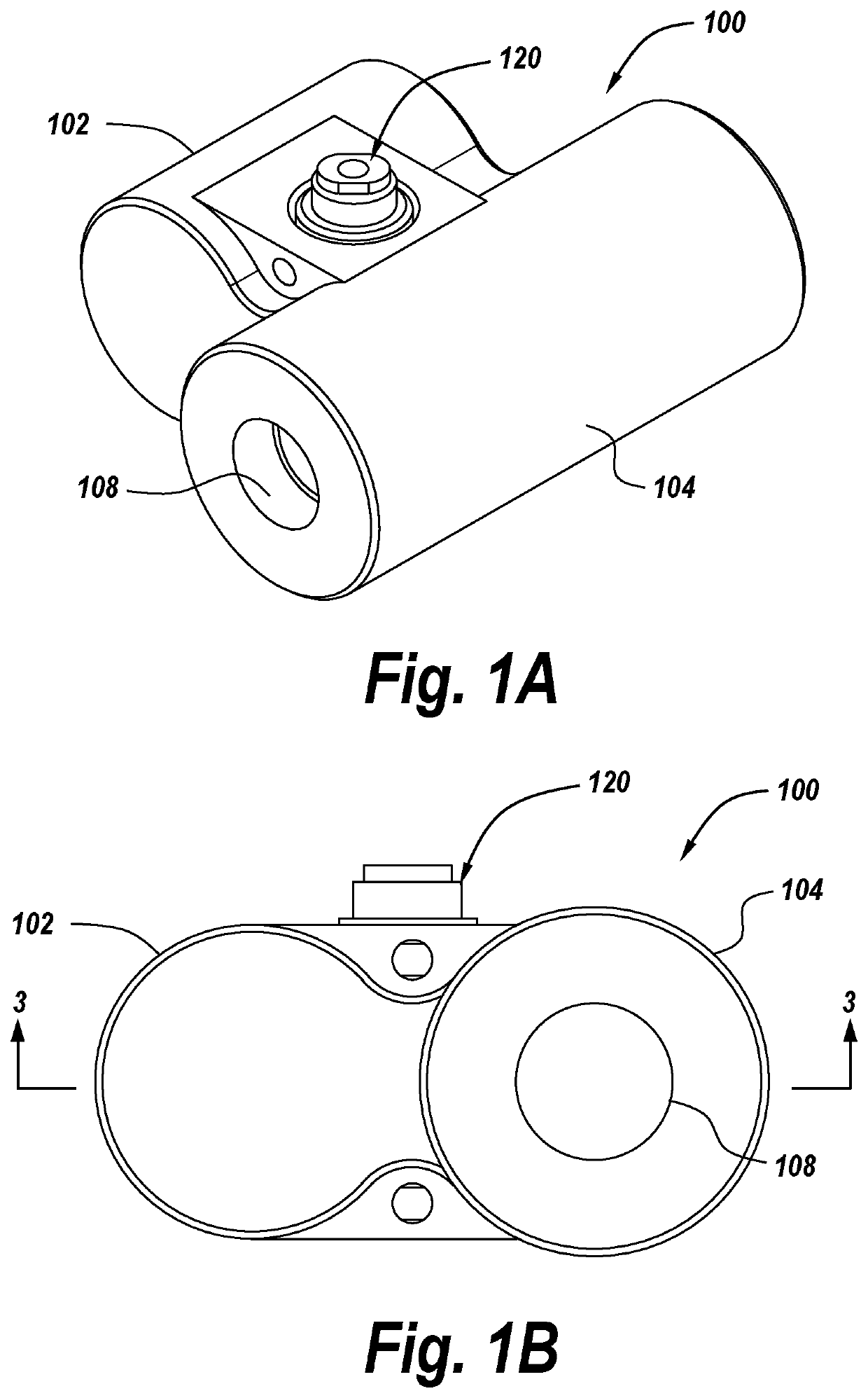
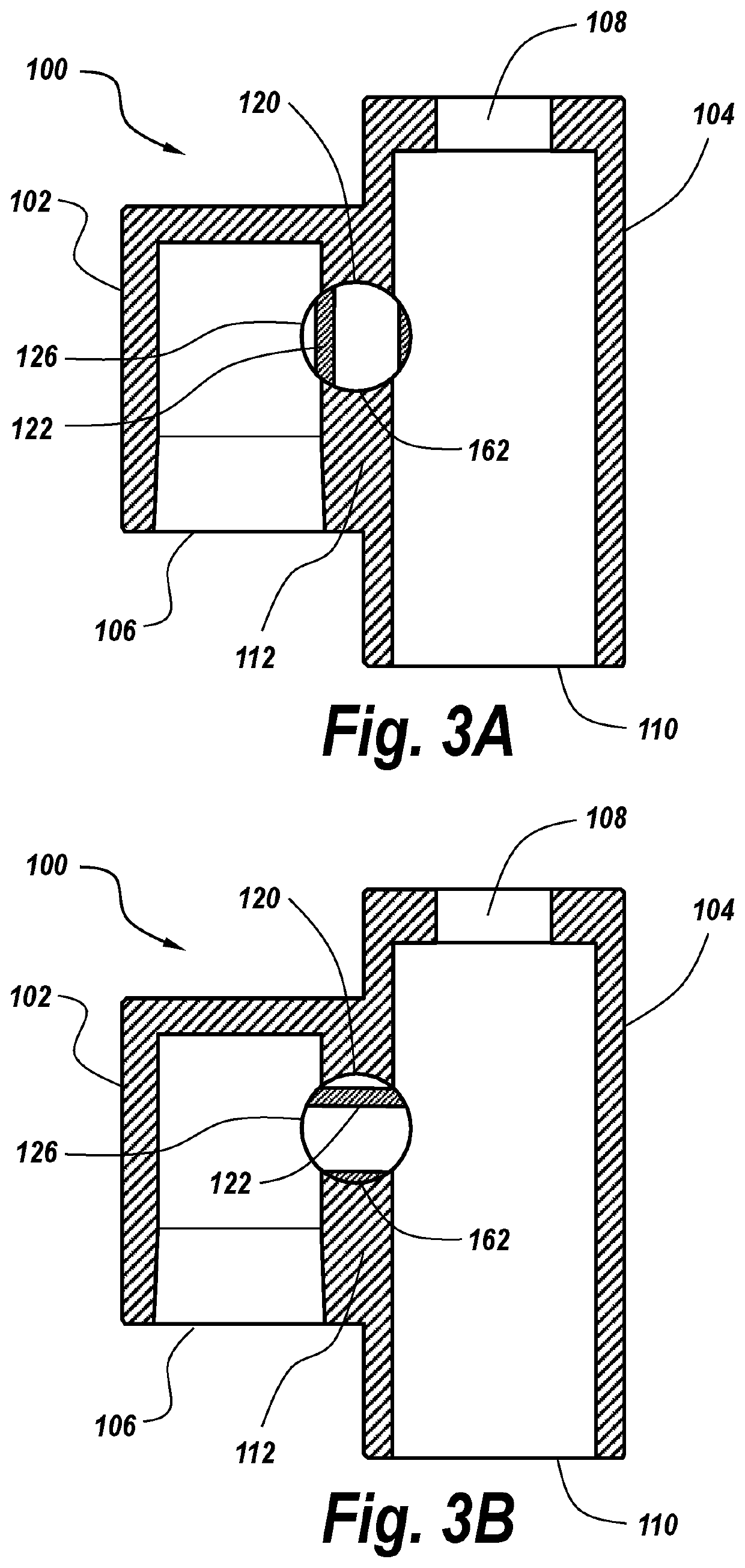
[0024]FIGS. 1A and 1B show a particular embodiment of a distribution manifold 100 having a valve assembly 120 disposed therein according to the present disclosure. The illustrated manifold includes first and second mutually parallel flow channels 102, 104, the flow channels being in selective mutual communication via the valve assembly. The manifold is also visible in a horizontal section views in FIGS. 3A and 3B.

[0025]In the illustrated embodiment, the first flow channel 102 terminates within the manifold, opposite an open end 106, while the second flow channel 104 has dual open ends 108, 110, though the presently disclosed valve assembly 120 is operable in association with other manifold embodiments as well. Each flow channel open end may be provided with suitable features to facilitate the selective coupling of fluid-conveying members such as hoses, tubes or pipes. These features may be, for example, mutually cooperating threads disposed on or in a manifold open end and on or in ...


PUM


Abstract

A barrel valve assembly for a fluid distribution manifold. A barrel valve body has an off-axis passage with substantially linear walls therethrough, allowing for a substantially linear relationship between fluid flow through the body and angular rotation of the barrel valve within the manifold. The barrel valve thus requires a smaller working environment for the valve assembly, providing benefits in terms of assembly size and weight.

Description

CROSS-REFERENCE TO RELATED APPLICATION[0001]This application claims the benefit of priority U.S. Provisional Application No. 62 / 983,260, filed on Feb. 28, 2020, the entirety of which is incorporated herein by reference.BACKGROUND[0002]Current air distribution manifolds can be large, heavy, and bulky. Typically, commercially available valves are associated with fluid flow channels through modules external to a manifold or housing containing the flow channels, thus increasing the volume required to accommodate such a valved manifold.[0003]Further, precise metering of flow volumes using currently available valves, such as ball valves, is challenging. This is attributable to the fact that a given angular rotation of a common valve results in differing changes in flow volumes, depending upon how far the valve is already open or closed. For example, a typical ball valve utilizes a round port. If the valve is closed, a given angular rotation of the valve in the open direction will reveal a...

Claims


Application Information

Patent Timeline
IPC IPC(8): F16K5/02
CPCF16K5/0207F16K5/0407F16K11/085
Inventor TANKERSLEY, ADAM DREWGUZOWSKI, JESSE ANDREW
Owner COLUMBIA INSURANCE CO
Why Eureka
Try Eureka