Subtalar Joint Prostheseis and Its Method of Implantation

Active Publication Date: 2015-02-19
SCHON LEW C +4
View PDF2 Cites 5 Cited by
  • Summary
  • Abstract
  • Description
  • Claims
  • Application Information

AI Technical Summary

Benefits of technology

The patent text describes a design for medical components that are strong and rigid enough to require minimal bone resection during their implantation. The goal is not to make the components thinner, but rather to minimize their thickness while still providing necessary strength and rigidity.

Problems solved by technology

Severe pain in this joint can also cause instability, limping and wear on other joints.
It is known that limiting the motion in one joint will result in greater load distribution in adjacent joints, which can further degenerative disease.
The size of the prosthesis will typically result in the resection of a significant amount of bone and the compromising of adjoining critical bony and soft tissue structures.
This situation can lead to the diminishment over time of the stability of the orientation of such prosthesis and their ultimate failure.
Despite the development of many types of ankle joint prostheses, none has ever been developed for the subtalar joint.

Method used


Image

  • Subtalar Joint Prostheseis and Its Method of Implantation
  • Subtalar Joint Prostheseis and Its Method of Implantation
  • Subtalar Joint Prostheseis and Its Method of Implantation

Examples


Embodiment Construction

[0025]Before explaining at least one embodiment of the present invention in detail, it is to be understood that the invention is not limited in its application to the details of construction and to the arrangements of the components set forth in the following description or illustrated in the drawings. The invention is capable of other embodiments and of being practiced and carried out in various ways. Also, it is to be understood that the phraseology and terminology employed herein are for the purpose of description and should not be regarded as limiting.

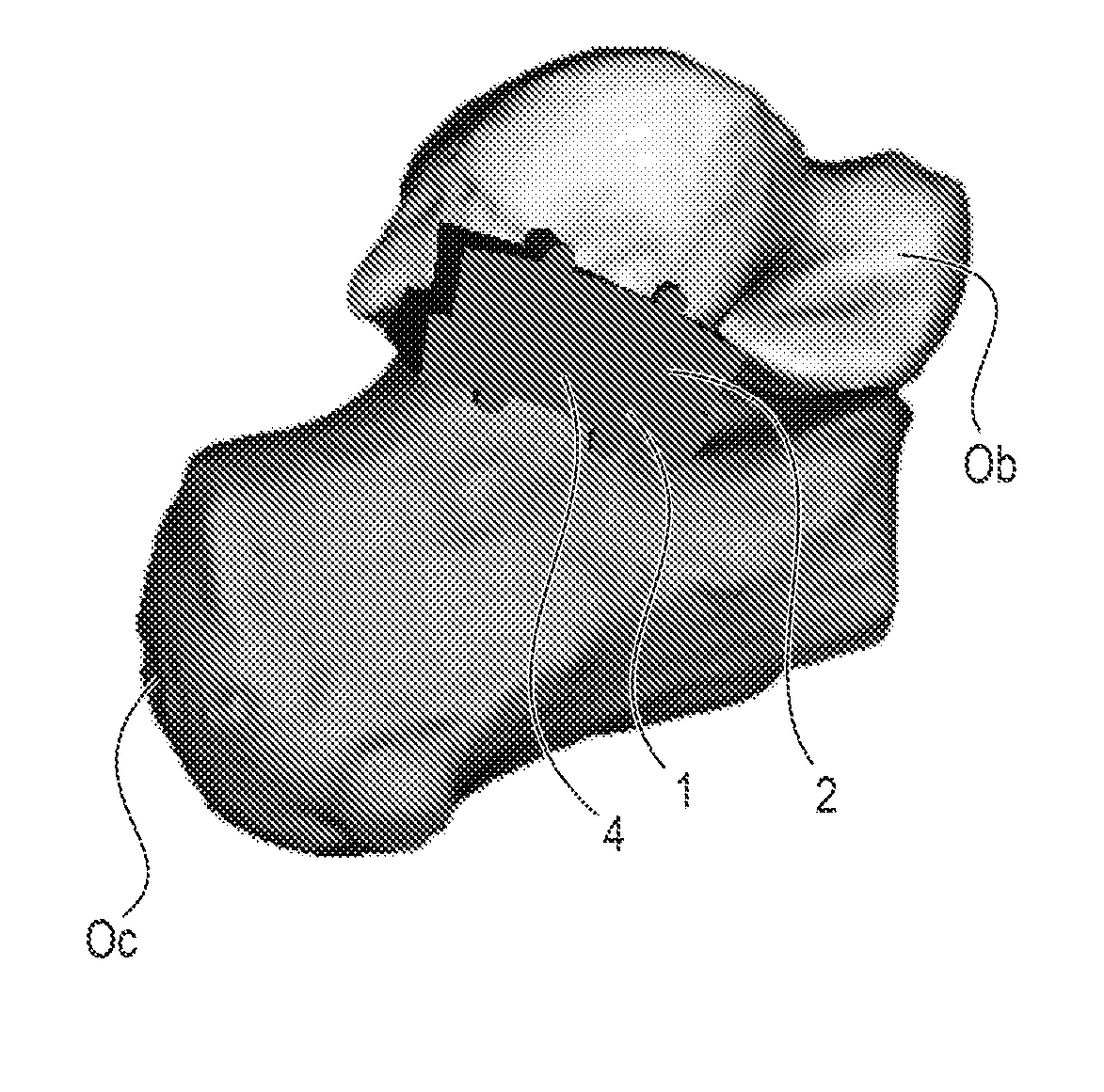
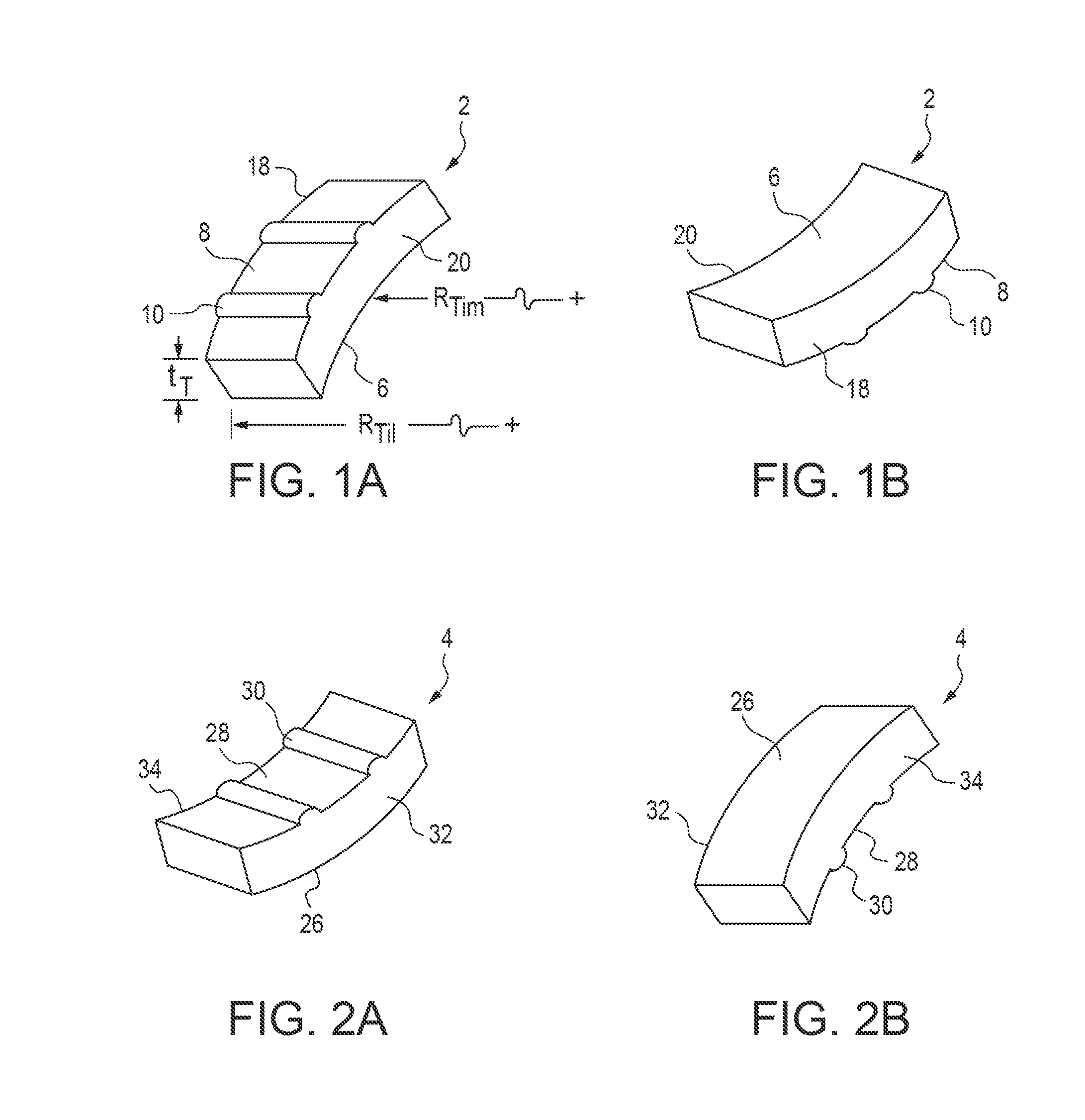
[0026]In a preferred embodiment, the subtalar joint prosthesis 1 of the present invention includes talar 2 and calcaneal 4 components. See FIGS. 1A-1B and 2A-2B. These components are designed so as to allow the subtalar joint prosthesis of the present invention to reproduce natural subtalar joint motion.

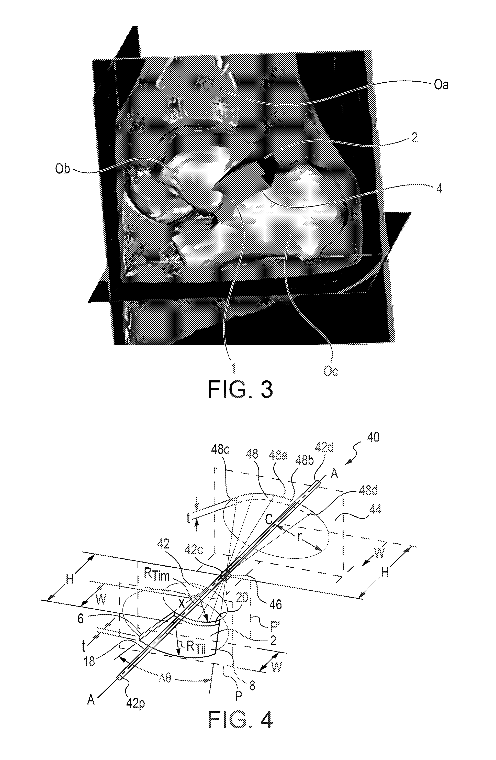
[0027]FIG. 3 shows these components after they have been implanted in the subtalar joint. Shown is a generally medially to lateral...


PUM


Abstract

A subtalar joint prosthesis that is adapted to replace the natural subtalar joint that exists between a patient's talus and calcaneus bones includes talar and calcaneal components. Each of these is configured to have a shape that is herein defined as being a portion of the boundary surface of a frustum. Meanwhile, these components' inner surfaces are configured to: (a) generally follow the anatomic contour of the original joint surface to which each component is to be attached, and (b) minimize each components's average thickness, consistent with providing sufficient strength and rigidity for the components, so as to require minimum bone resection for the implantation of these components.

Description

CROSS-REFERENCE TO RELATED APPLICATION[0001]This application claims the benefit of PCT Patent Application No. PCT / US2011 / 047716, filed Aug. 15, 2011 by the present inventors. The teachings of this earlier application are incorporated herein by reference to the extent that they do not conflict with the teaching herein.BACKGROUND OF THE INVENTION[0002]1. Field of the Invention[0003]This invention relates to surgery and orthopedic instrumentation. More particularly, this invention relates to a subtalar joint prosthesis and the surgical procedure and apparatus for its implantation.[0004]2. Description of Prior Art[0005]For many years there has been considerable interest and activity with respect to joint replacement in the foot and ankle, in which the degenerative articular surfaces of a joint are removed and replaced with an artificial joint, called a prosthesis, as a viable approach for the treatment of diseased or injured joints. Among the joints that can be considered for treatment ...

Claims


Application Information

Patent Timeline
IPC IPC(8): A61F2/42
CPCA61F2/4225A61F2/4202A61F2002/30879A61F2002/4207A61F2002/4217A61F2002/4223
Inventor SCHON, LEW C.CHIODO, CHRISTOPHERPARKS, BRENT G.AARON, DAVIDDINE, ZEYNEP B.
Owner SCHON LEW C
Why Eureka
Try Eureka