Illumination device and liquid crystal display device

Inactive Publication Date: 2010-09-02
PANASONIC CORP
View PDF4 Cites 1 Cited by
  • Summary
  • Abstract
  • Description
  • Claims
  • Application Information

AI Technical Summary

Benefits of technology

[0029]Because the distances between the bulbs and the external electrode are regularly varied seen from the bulb axial lines, high lev

Problems solved by technology

Further, as shown in FIG. 19B, even when all optical sheets are used, the effect of irregular variation in brightness among the lamps 1 causes non-uniformity in brightness.
This non-uniformity in brightness results in non-uniformity in brightness of images displayed on the liquid crystal panel 12.
As discussed above, the direct backlight device using the internal-external type lamps having the gap between the bulbs and the external electrode can not achieve adequate brightness uniformity when the intervals between adjacent lamps are certain level of narrow, that is, when the lamps are arranged densely at certain level.
On the other hand, when the intervals between adjac

Method used


Image

  • Illumination device and liquid crystal display device
  • Illumination device and liquid crystal display device
  • Illumination device and liquid crystal display device

Examples


Example

First Embodiment

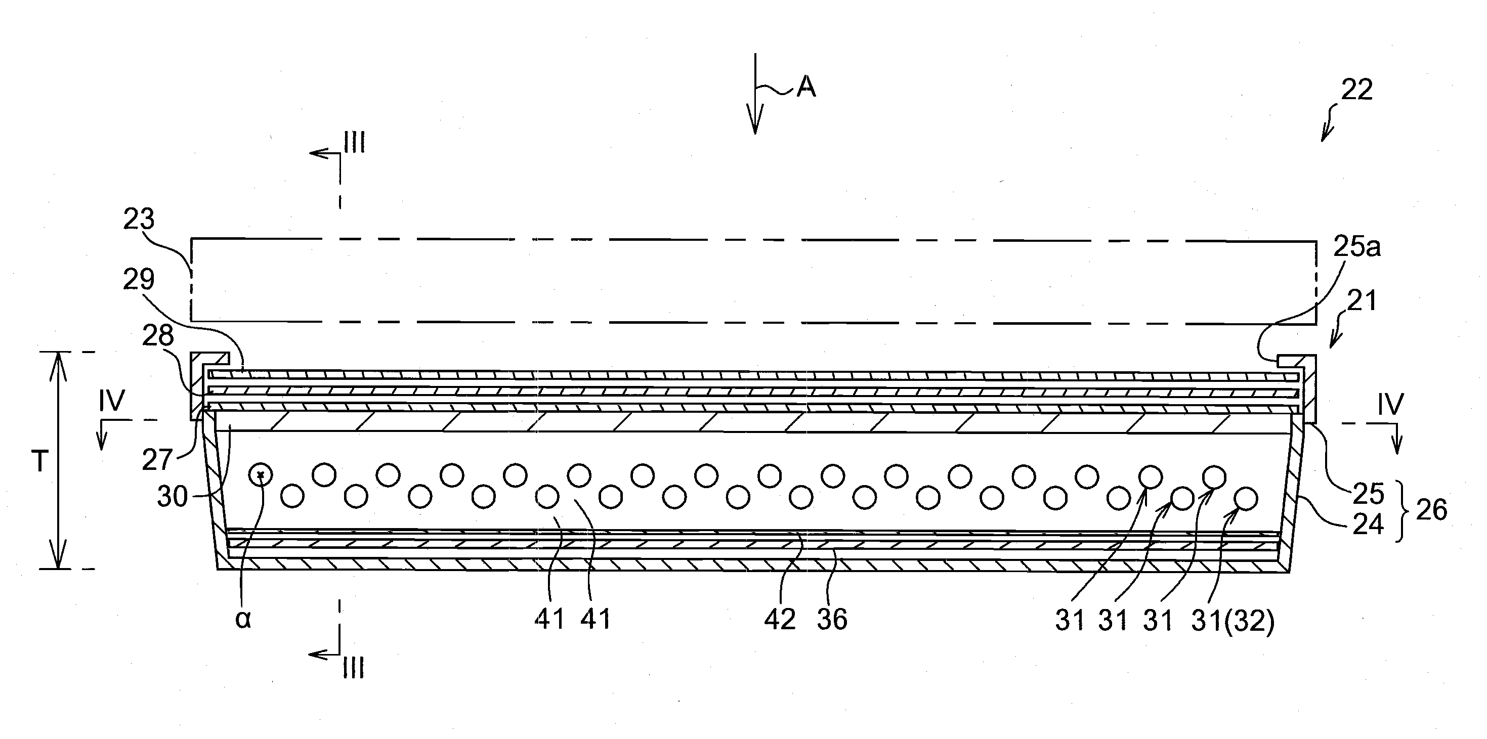
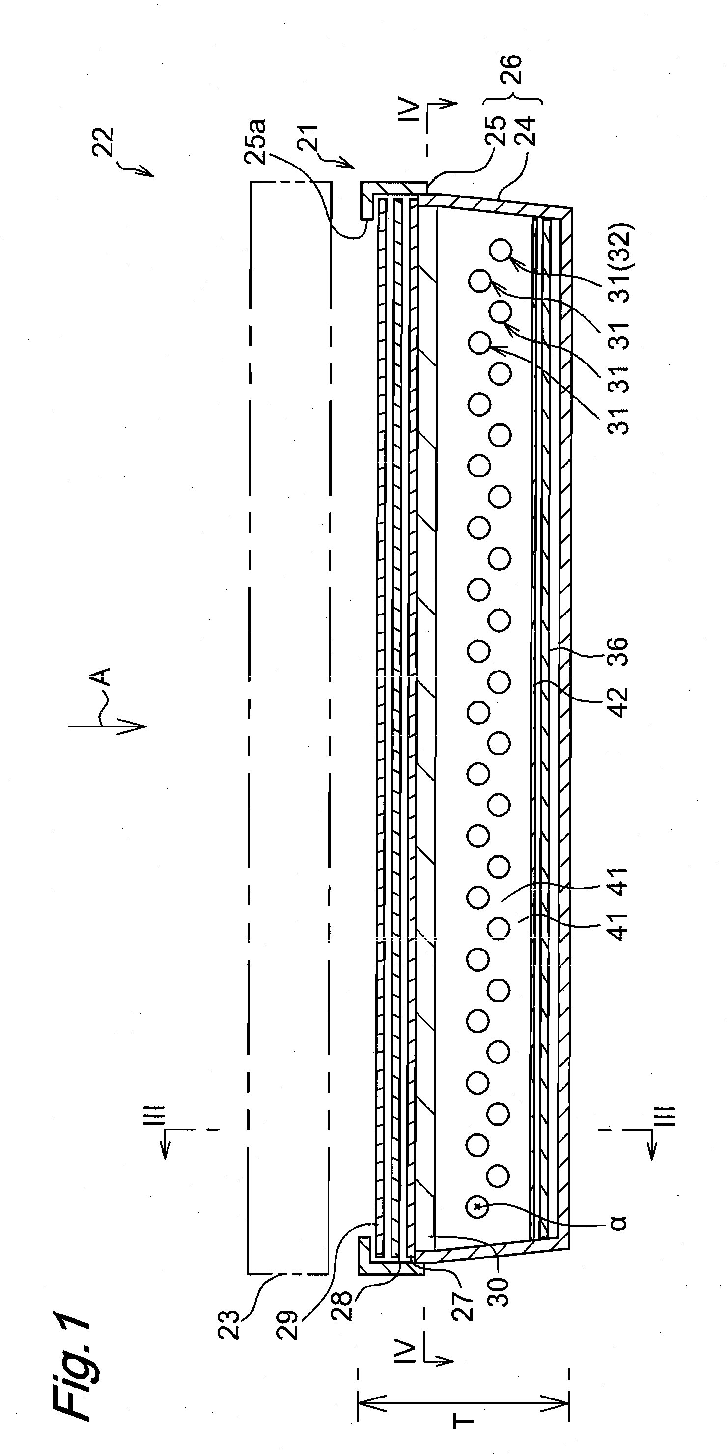
[0078]FIG. 1 through 4 show a liquid crystal display device 22 comprising a backlight device 21 according to a first embodiment of an illumination device of the present invention. The backlight device 21 is disposed on a rear-face side of a liquid crystal panel 23 shown in FIG. 1.

[0079]The backlight device 21 is provided with a casing 26 consisting of a main body 24 and cover member 25. Accommodated in the casing 26 (near an opening portion of the main body 24) is an acrylic diffusion plate 30. Further, accommodated above the acrylic diffusion sheet 30 in stack manner are three optical sheets, i.e., a diffusion sheet 27, a lens sheet 28, and a DBFE (Dual Brightness Enhancement Film) 29. The cover member 25 is provided with a window portion 25a to expose the optical sheets. A front-face side of the optical sheets is opposed to the liquid crystal panel 23 through the window portion 25a.

[0080]In order to efficiently pass light to the liquid crystal panel 23, the diffus...

Example

Second Embodiment

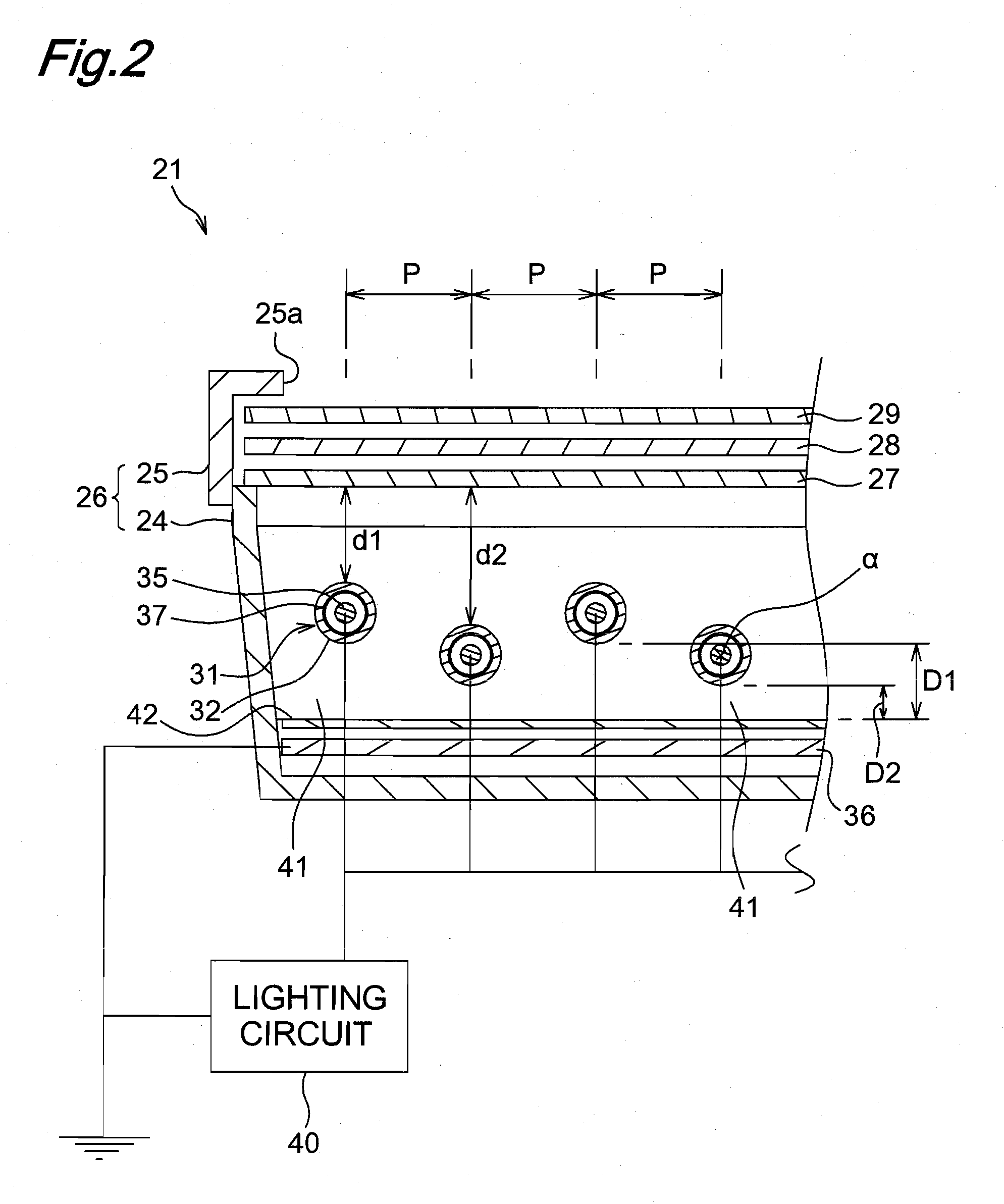
[0121]FIG. 10 shows the backlight device 21 of a second embodiment of the present invention. In this first embodiment, the bulbs 32 are arranged on a regular polygonal line “δ” seen from the direction of the axial lines “α” of the bulbs 32. Specifically, the backlight device 21 are provided with, in addition to the bulbs 32 the distance from which to the external electrode 36 is the first distance “D1” and the bulbs 32 the distance from which to the external electrode 36 is the second distance “D2” shorter than the first distance “D1”, bulbs 32 arranged intermediately between the bulbs 32 at the distance “D1” and the bulbs 32 at the distance “D2” and having a distance “D3”. Seen from the direction of the axial lines “α”, the bulbs 32 are arranged with the fixed interval “P” so that the distances “D1”, “D3”, “D2”, and “D3” are repeated in this order from the left side to the right side in FIG. 10.

[0122]Since other configurations and functions of the second embodiment...

Example

Third Embodiment

[0123]FIG. 11 shows the backlight device 21 of a third embodiment of the present invention. In the third embodiment, bulbs 32 are arranged on a sinusoidal curve “φ” seen from the direction of the axial lines “α” of the bulbs 32. Specifically, the backlight device 21 are provided with, in addition to the bulbs 32 the distance from which to the external electrode 36 is the first distance “D1” and the bulbs 32 the distance from which to the external electrode 36 is the second distance “D2” shorter than the first distance “D1”, bulbs 32 arranged intermediately between the bulbs 32 at distances “D1” and “D2 (at distance “D3”), bulbs 32 arranged intermediately between the bulbs 32 at distances “D1” and “D3” (at distance “D4”), and bulbs 32 arranged intermediately between bulbs 32 at distances “D2” and “D3” (at distance “D5”). Seen from the direction of the axial line “α”, the bulbs are arranged with the fixed interval so that the distances “D1”, “D4”, “D3”, “D5”, “D2”, “D5...


PUM


Abstract

A backlight device 21 is an illumination device having a plurality of internal-external electrode type dielectric barrier discharge lamps. The backlight device 21 has a plurality of internal electrodes respectively arranged inside each of bulb 32 and connected in parallel to a lighting circuit 40 for outputting an AC driving voltage, and an external electrode arranged outside each of the bulbs 32 with a gap 41 and grounded. Holding members 43A to 43C holds the bulbs 32 so that distances between the bulbs 32 and the external electrode 36 are regularly varied seen from a direction of the axial line of the bulb 32.

Description

TECHNICAL FIELD [0001]The present invention relates to an illumination device such as a backlight device for illuminating a liquid crystal display device, an illumination device for illuminating an original in apparatuses including a facsimile machine and copier, or general illumination device. Further, the present invention relates to a liquid crystal display device provided with such an illumination deice as a backlight device.[0002]Recently, researches on lamps not using mercury (hereinbelow referred to as mercury-free type) as a lamp (or light source devices) for light source device such as a back light device of a liquid crystal display device is actively progressing, in addition to researches on lamps using mercury for such usage. The mercury-free type lamps are preferable due to low fluctuation of light emission intensity along with time variation of temperature and in view of consideration of environments.[0003]One of known mercury-free lamps is a so-called an internal-exter...

Claims


Application Information

Patent Timeline
IPC IPC(8): G02F1/1335H05B41/24
CPCG02F1/133611G02F1/133604
Inventor OHKUBO, KAZUAKIHASHIMOTODANI, KIYOSHI
Owner PANASONIC CORP
Why Eureka
Try Eureka