

Poppet valve
a technology of poppet valve and poppet valve body, which is applied in the direction of functional valve types, machines/engines, positive displacement liquid engines, etc., can solve the problems of relatively high wear of poppet valve, relatively large installation height, and relatively high pressure loss of poppet valve, so as to reduce the force, reduce the weight of moving parts, and reduce the effect of inertia
- Summary
- Abstract
- Description
- Claims
- Application Information
AI Technical Summary
Benefits of technology
Problems solved by technology
Method used
Image

Examples
Embodiment Construction
[0003]It is the object of the invention to embody a poppet valve which has more advantageous operating characteristics.
[0004]This object is achieved by means of a poppet valve having the features of claim 1. Dependent claims 2 to 15 relate to further advantageous embodiments of the invention.
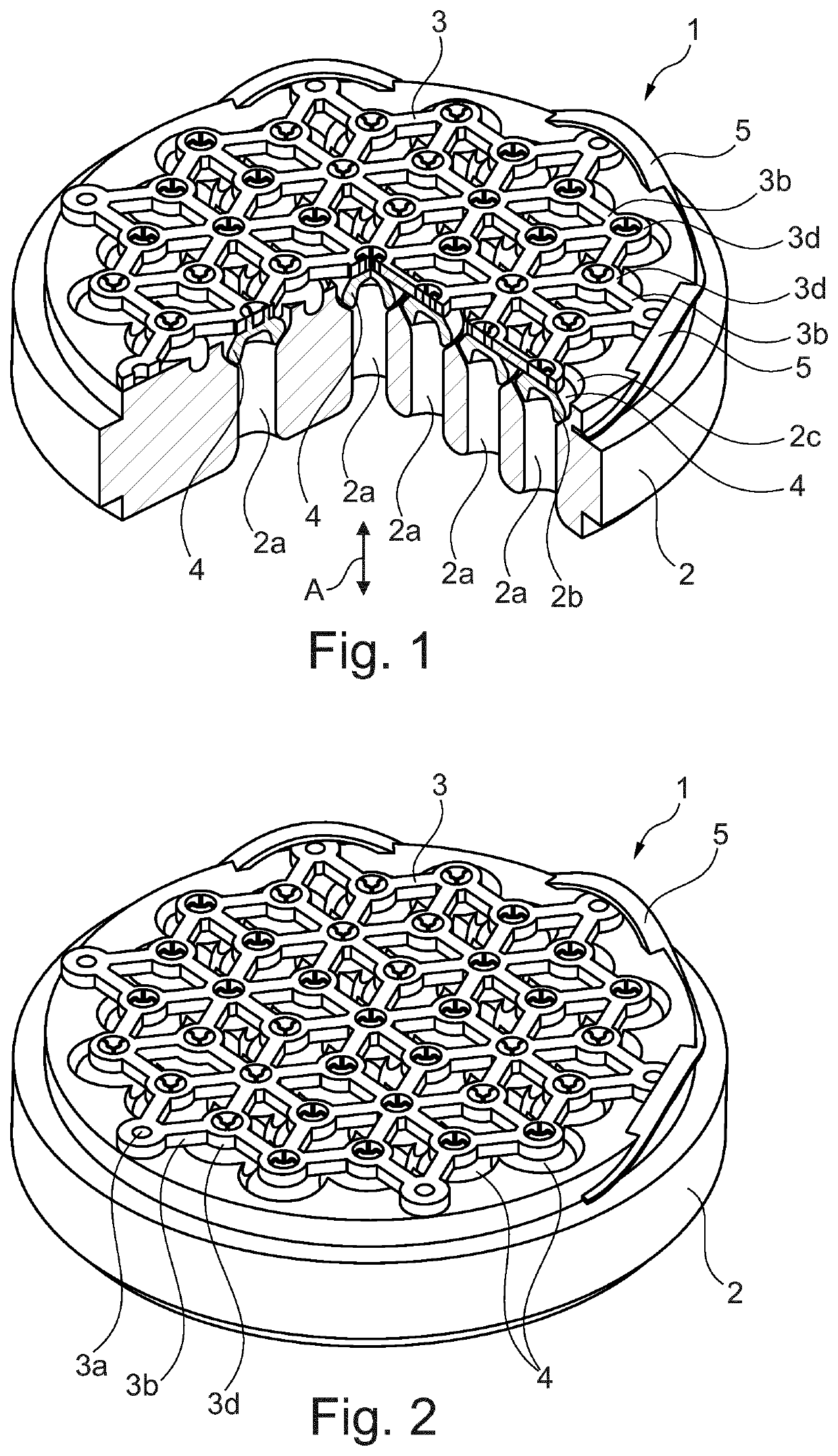
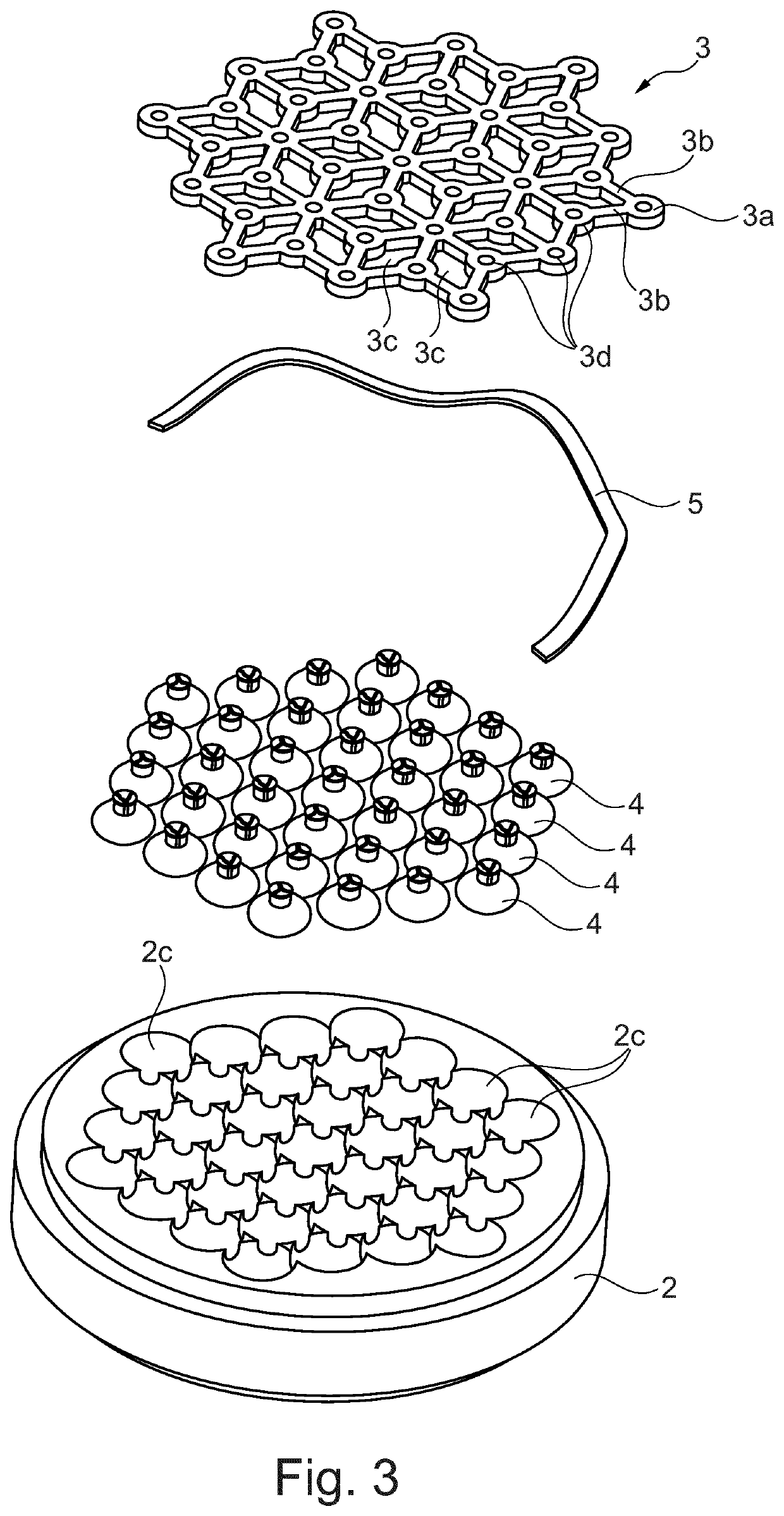
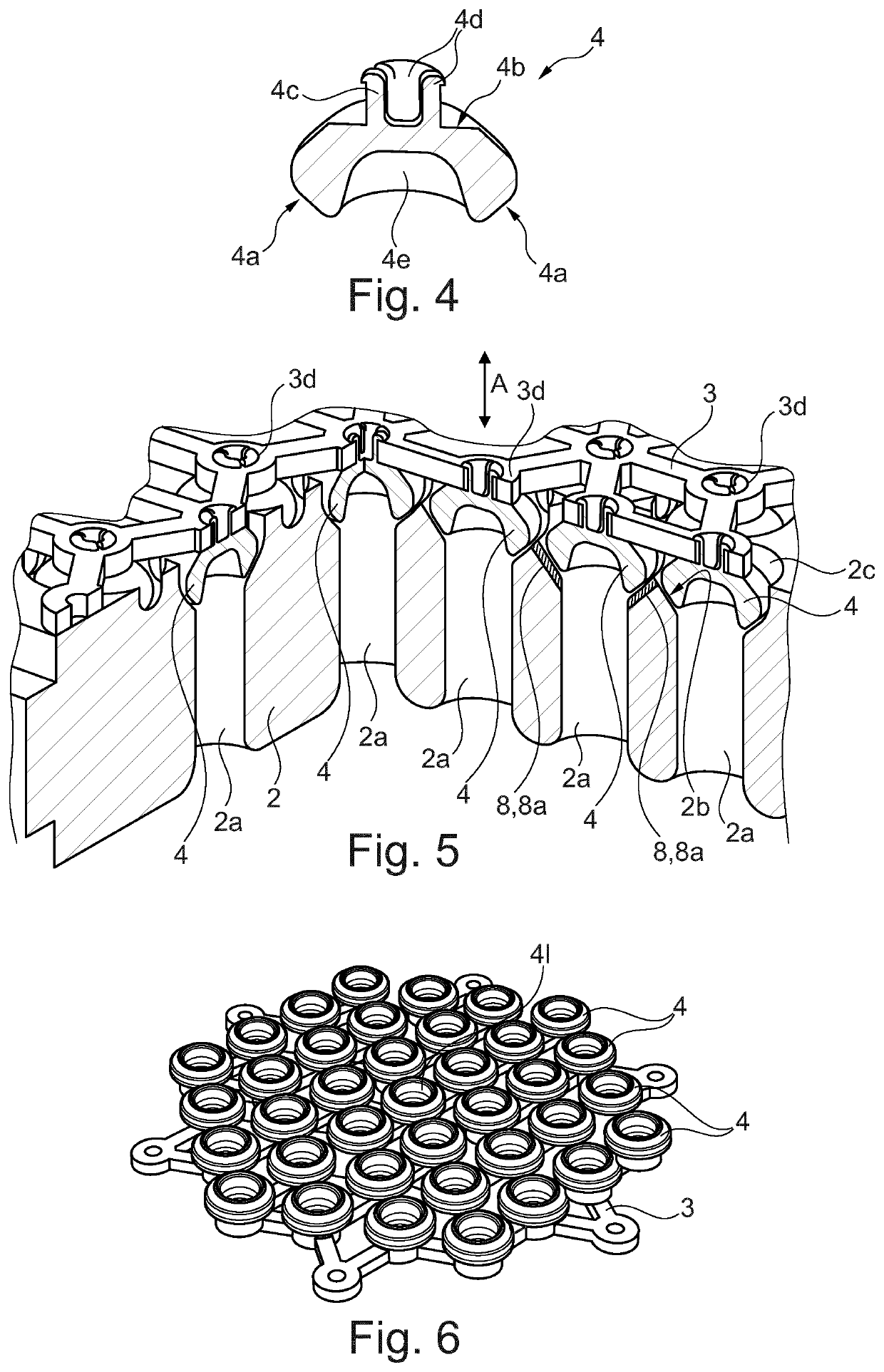
[0005]In particular, the object is achieved by a poppet valve comprising a valve seat cover having a plurality of inlet channels, wherein each inlet channel opens into a valve seat, and comprising a plurality of closing elements, which are movable in an axial direction, wherein a closing element is associated with each valve seat, and wherein each valve seat is arranged opposite the associated closing element in the axial direction, such that each valve seat is closable by the associated closing element, wherein all the closing elements are arranged on a common closing element holding device, and wherein the closing element holding device is movable in the axial direction in such a way that the ...
PUM
 Abstract
Description
Claims
Application Information