Sprocket
a technology of sprockets and sprockets, which is applied in the direction of driving chains, gearing, hoisting equipment, etc., can solve the problems of vibration and noise in the entire chain driving gear, and achieve the effects of reducing vibration and noise, reducing impact and striking sound, and improving durability
- Summary
- Abstract
- Description
- Claims
- Application Information
AI Technical Summary
Benefits of technology
Problems solved by technology
Method used
Image
Examples
embodiment 1
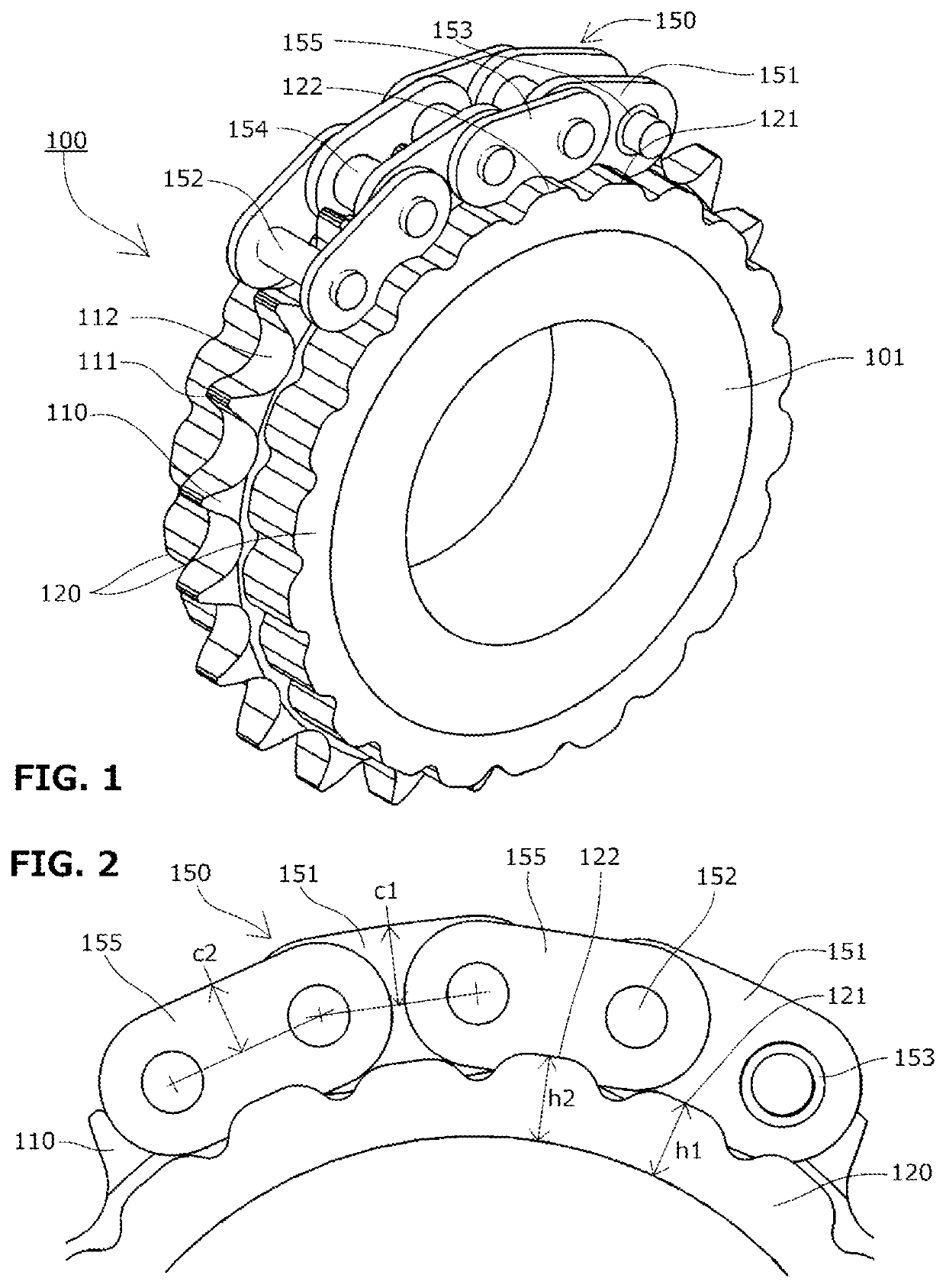
[0029]A sprocket 100 according to a first embodiment of the present invention includes, as shown in FIGS. 1 and 2, a sprocket main body 101, on the circumferential surface of which a plurality of teeth 110 including tooth tips 111 and teeth bottoms 112 are formed, and cushion rings 120 that is made of an elastic member and is provided on both side surfaces of the sprocket main body 101. The outer circumferences of a cushion ring 120 comes into contact with the link plates of the chain.
[0030]First convex sections 121 and second convex sections 122 are alternately provided in the circumferential direction in the outer circumferences of the cushion rings 120 on both the side surfaces. They are formed so that the centers of the first convex sections 121 and the second convex sections 122 be located at corresponding positions to the tooth tips 111.
[0031]Herein, the term “corresponding positions” in the circumferential direction refers to positions having identical angles in the circumfer...
embodiment 2
[0038]A sprocket according to a second embodiment of the present invention has the same configuration as the sprocket according to the first embodiment except that the cushion ring 120B is installed.
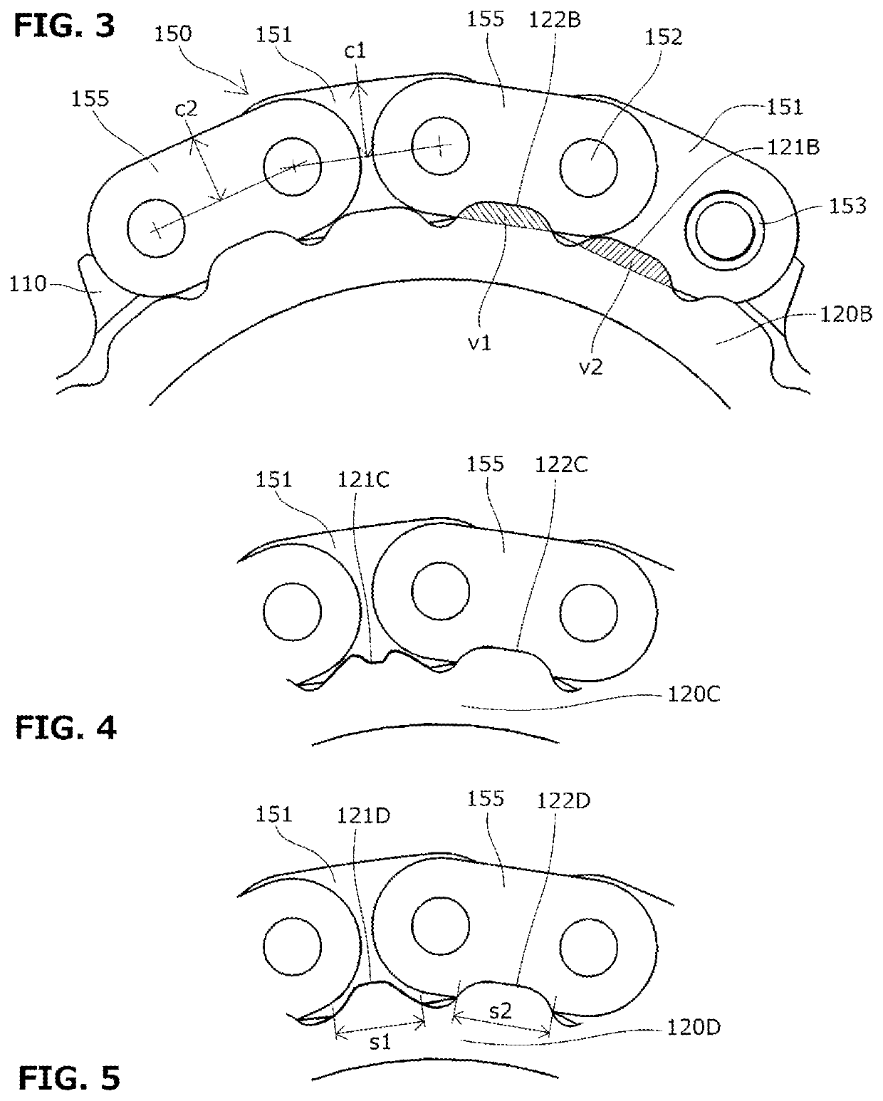
[0039]The cushion ring 120B of the sprocket according to the second embodiment is formed such that, as shown in FIG. 3, an interference amount (volume) v1 between a first convex section 121B and the inner link plate 151 be equal to an interference amount (volume) v2 between a second convex section 122B and the outer link plate 155 at the time when the chain 150 is seated.
[0040]With this configuration, even when the heights of the inner link plate 151 and the outer link plate 155 are different, it is possible to equalize reaction forces applied from the cushion ring 120B to the link plates and to suppress vibration due to a difference in reaction forces between the inner link plate 151 and the outer link plate 155.
embodiment 3
[0041]As shown in FIG. 4, a sprocket according to a third embodiment of the present invention has the same configuration as the sprocket in the first or second embodiment except that the cushion ring 120C is installed.
[0042]The cushion ring 120C of the sprocket according to the third embodiment is formed such that the shape of a first convex section 121C to which the inner link plate 151 interferes be different from a shape of a second convex section 122C to which the outer link plate 155 interferes
PUM
 Abstract
Description
Claims
Application Information
 - R&D
- Intellectual Property
- Life Sciences
- Materials
- Tech Scout
- Unparalleled Data Quality
- Higher Quality Content
- 60% Fewer Hallucinations
Browse by: Latest US Patents, China's latest patents, Technical Efficacy Thesaurus, Application Domain, Technology Topic, Popular Technical Reports.
© 2025 PatSnap. All rights reserved.Legal|Privacy policy|Modern Slavery Act Transparency Statement|Sitemap|About US| Contact US: help@patsnap.com


