
Check valve

a check valve and valve body technology, applied in the field ofpetroleum engineering, can solve the problems of reducing the energy efficiency of the pump, preventing the seat from being pressed firmly against the seat, etc., and achieve the effect of reducing the hydraulic resistance of the valv

Active Publication Date: 2020-02-27
OKLAS TECH LLC
View PDF0 Cites 1 Cited by
  • Summary
  • Abstract
  • Description
  • Claims
  • Application Information

AI Technical Summary

Benefits of technology

The invention is a ball check valve that solves problems with reliability and energy efficiency. The valve has a hollow cylindrical housing with a protrusion and a seat ring with a ball locking element. It also has a stoke limiter in the form of a cage with through holes for fluid flow. An elastic element is mounted between the seat ring and the cage. This design prevents additional forces from acting on the ball locking element in the open position, reducing hydraulic resistance. The technical effects of the invention are increased reliability and energy efficiency, resulting in increased valve life and improved energy efficiency during operation.

Problems solved by technology

The main disadvantage of these devices is that during operation, when closing the valve, mechanical impurities contained in the formation fluid can interfere with the hermetic closure of the shut-off element, preventing it from being pressed firmly against the seat.
The disadvantage of this valve is that during operation of the pump, the valve is in the open position.
The fluid flow compresses the spring, which increases the hydraulic resistance of the valve to the flow and reduces the energy efficiency of the pump.

Method used


Image

  • Check valve
  • Check valve
  • Check valve

Examples


Embodiment Construction

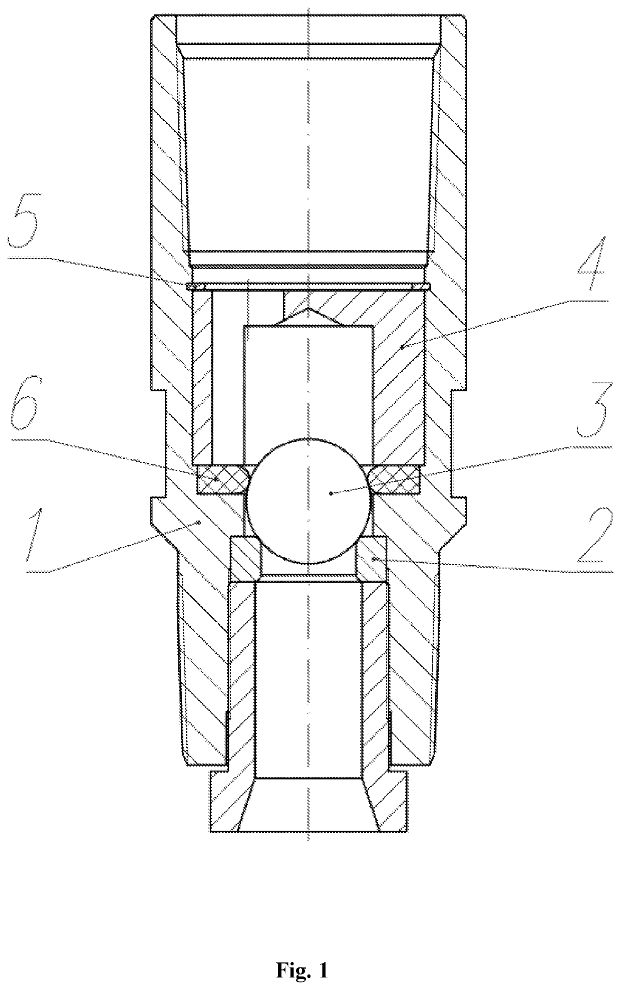
[0017]In the preferred embodiment, the check valve (FIG. 1) contains the housing 1 in which a valve pair is mounted, consisting of the seat 2 and the ball locking element 3. The stroke limiter of the locking element is made in the form of the cage 4 with through holes for the fluid flow. The cage 4 is fixed in the housing by means of the retaining ring 5. Between the cage 4 and the seat 2 there is the annular elastic element 6 having a semicircular shape in longitudinal section.

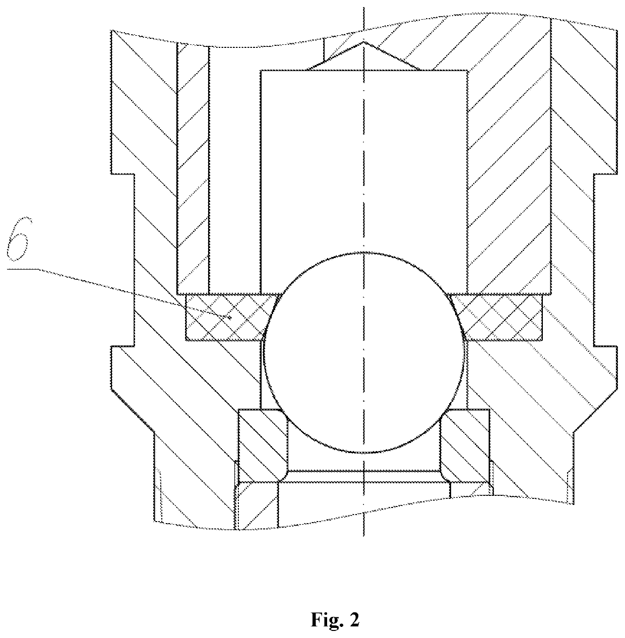
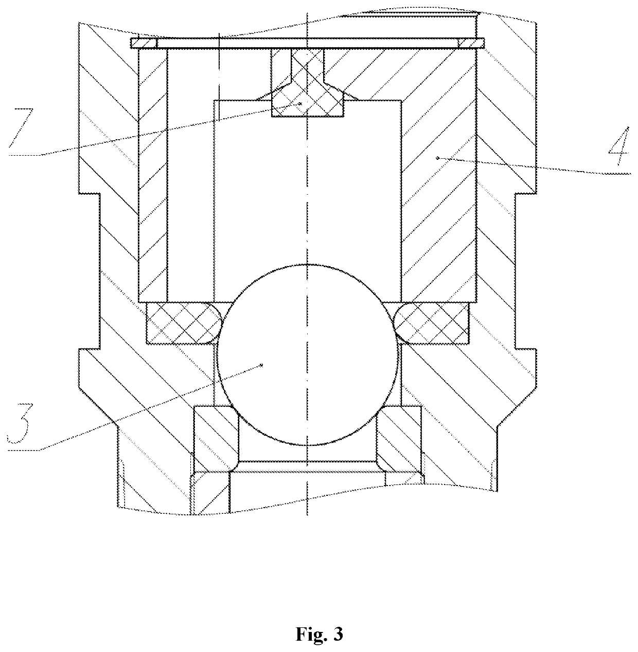
[0018]FIG. 2 shows the elastic element 6 having a conical shape in longitudinal section. FIG. 3 shows the design of the valve with the damping element 7 mounted in the cage 4.

[0019]The check valve operates as follows. After the pump is turned on, pressure is created under the ball locking element 3 (FIG. 1), the ball locking element 3 rises from the seat 2 overcoming elastic forces from the annular elastic element 6, and moves upward along the cage 4, opening the valve for the passage of the pumped liquid. Af...


PUM


Abstract

The invention relates to petroleum engineering, and more particularly to the design of a check valve that can be used in conjunction with downhole sucker-rod pumps or electric centrifugal pumps primarily intended for pumping fluids with a high solid particle content. A ball check valve comprises: a hollow cylindrical housing having an internal annular protrusion; a valve pair mounted inside said housing and being in the form of an annular seat and a ball locking member; and a means for limiting the movement of the closure member, which is in the form of a cage with through holes for fluid flow. Between the seat and the cage there is mounted an annular elastic member, the inner diameter of which is not greater than the diameter of the ball locking member. The annular elastic element performs a dual function: when closing the valve provides additional pressing of the ball locking element to the seat due to the arising elastic forces; and provides additional sealing. Also, in the open position, additional forces do not act on the ball locking element, which reduces the hydraulic resistance of the valve. Thus, the use of an annular elastic element in the design of the check valve increases the valve life and increases its energy efficiency during operation.

Description

FIELD OF THE INVENTION[0001]The present invention relates to petroleum engineering, in particular to the design of the check valve, which can be used with sucker-rod or centrifugal pumps designed for pumping liquids with a high content of mechanical impurities.BACKGROUND[0002]Known are check valves described in patents for utility model RU55018, RU56940, RU70544, RU76380, RU83799, RU100579.[0003]The main disadvantage of these devices is that during operation, when closing the valve, mechanical impurities contained in the formation fluid can interfere with the hermetic closure of the shut-off element, preventing it from being pressed firmly against the seat.[0004]The closest in technical essence to the invention is a ball check valve, comprising a hollow cylindrical body with an internal annular protrusion, a valve pair installed in the body in the form of an annular seat and a ball locking element, the stroke limiter of the locking element in the form of a cage with through holes fo...

Claims


Application Information

Patent Timeline
IPC IPC(8): F16K15/04
CPCF16K15/04E21B34/06F16K15/046F16K2200/30
Inventor LEONOV, VYACHESLAV VLADIMIROVICH
Owner OKLAS TECH LLC
Learn More