Travel Route Management System and Travel Route Determination Device

a technology of route management system and determination device, which is applied in the direction of process and machine control, navigation instruments, instruments, etc., can solve the problems of delay in work travel, inefficient work, and long time-consuming computation, and achieve the lowest total cost and quick and easy determination of selection order

Active Publication Date: 2020-02-27
KUBOTA LTD
View PDF0 Cites 36 Cited by
  • Summary
  • Abstract
  • Description
  • Claims
  • Application Information

AI Technical Summary

Benefits of technology

[0038]As described above, with a basic priority rule, which is favorable when employing a parallel line set as the travel route element set, a priority level from the travel route element previous in the order to the travel route element next in the order is set in advance. Preferably, this priority level is set so that a properly-distanced travel route element, which is a predetermined distance from the travel route element previous in the order, has the highest priority as the next element in the order. Furthermore, it is preferable that the priority level be set to decrease as the distance from the travel route element previous in the order to the travel route element next in the order increases. Using such a basic priority rule makes it possible to quickly and easily determine the selection order for the travel route elements, and thus the computations end in a short amount of time even when there is a large number of travel route elements.
[0039]With respect to the cost evaluation rule used after the selection order calculation using the basic priority rule, preferably, a cost evaluated by the cost evaluation rule is a cost arising when the work vehicle travels on the travel route elements according to the selection order calculated by the second route element selecting unit; and a selection order where the cost is the lowest is calculated by the second route element selecting unit. In the field of route searching, a more appropriate selection order is obtained by using the cost evaluation rule to calculate a selection order providing the lowest total cost necessary when passing through each travel route element.

Problems solved by technology

It therefore takes a long time to obtain the computation results, which delays the start of the work travel.
However, it is highly likely that the work will be inefficient as a result.

Method used


Image

  • Travel Route Management System and Travel Route Determination Device
  • Travel Route Management System and Travel Route Determination Device
  • Travel Route Management System and Travel Route Determination Device

Examples


Embodiment Construction

Overview of Autonomous Travel

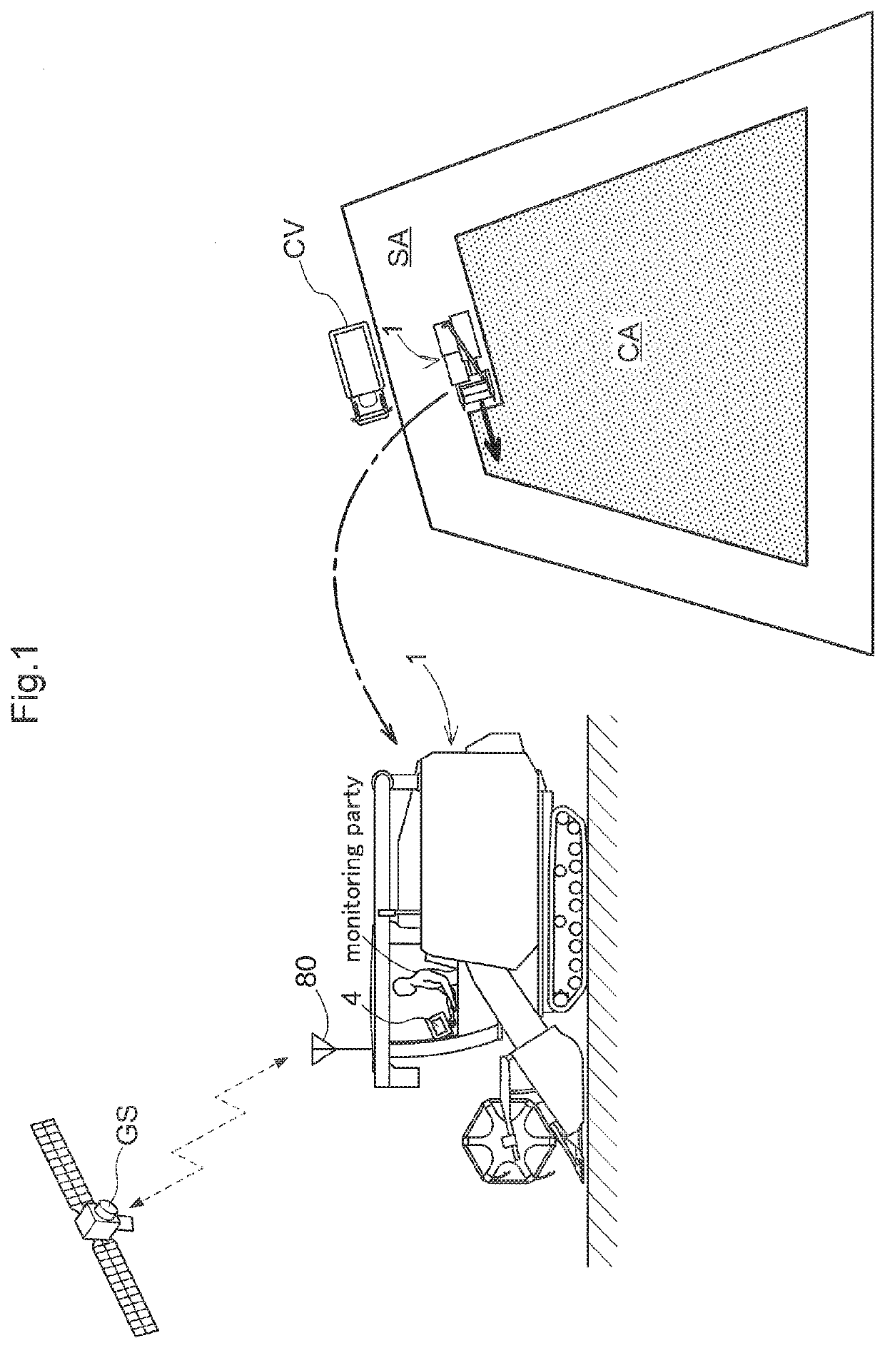
[0078]FIG. 1 schematically illustrates work travel using a travel route management system. In this embodiment, a work vehicle is a harvester 1 that, as work travel, carries out harvesting work (reaping work) for harvesting crops while traveling, and is a model typically called a normal-type combine. The work site where the harvester 1 travels for work is called a field. During harvesting work in the field, the area that the harvester 1 circles the border lines of the field, called a “ridge”, is set as an outer peripheral area SA. The inner side of the outer peripheral area SA is set as an area CA to be worked. The outer peripheral area SA is used as a movement space for the harvester 1 to unload harvested crops, refuel, and the like, as a space for switching directions, and so on. To set the outer peripheral area SA, the harvester 1 circles the border line of the field three or four times as initial work travel. In the circling travel, the field is worke...


PUM


Abstract

A travel route management system includes an area setting unit that sets a work site to an outer peripheral area SA and an area CA to be worked on an inner side of the outer peripheral area SA, and a route element selecting unit that sequentially selects a next travel route element to be traveled on next, from among multiple mutually-parallel travel route elements, the travel route elements constituting a travel route that covers the area CA to be worked. The route element selecting unit selects a U-turn travel route for moving from a travel route element serving as a movement origin to a next travel route element serving as a movement destination, the selection being made on the basis of an interval between the movement origin and the movement destination.

Description

TECHNICAL FIELD[0001]The present invention relates to a travel route management system that determines a travel route for a work vehicle that travels autonomously while working at a work site.[0002]The present invention furthermore relates to a travel route determination device that determines a travel route for a work vehicle that travels while working at a work site.BACKGROUND ART[0003][1] A field working machine disclosed in Patent Document 1 includes a route calculating part and a drive assist unit for working in a field while traveling autonomously. The route calculating part finds the outer shape of the field from topographical data. Then, on the basis of the outer shape and a work width of the field working machine, the route calculating part calculates a travel route that starts from a travel start point to a travel endpoint. The drive assist unit compares a vehicle position found from positioning data (latitude / longitude data) obtained from a GPS module with the travel rout...

Claims


Application Information

Patent Timeline
Patent Type & Authority Applications(United States)
IPC IPC(8): G01C21/34G05D1/00G05D1/02A01B79/00A01B69/04
CPCA01B79/005G01C21/3453G05D1/0088G05D1/0212A01B69/008A01B69/00A01D41/12A01D69/00B62D6/00G05D1/02G05D1/0219G05D2201/0201A01D41/127B62D15/025B62D15/0285
Inventor TOMITA, SAKURASANO, TOMOHIKOSAKAGUCHI, KAZUONAKAJIMA, TETSUYAOSHITANI, MAKOTOIWAMI, KENICHIYOSHIDA, OSAMU
Owner KUBOTA LTD
Why Eureka
Try Eureka