
Diaphragm structure and method of manufacturing the same

Active Publication Date: 2020-02-27
NAT TAIWAN UNIV OF SCI & TECH
View PDF0 Cites 0 Cited by
  • Summary
  • Abstract
  • Description
  • Claims
  • Application Information

AI Technical Summary

Benefits of technology

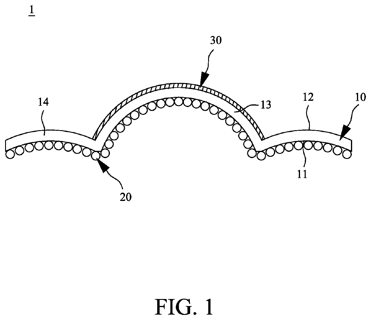
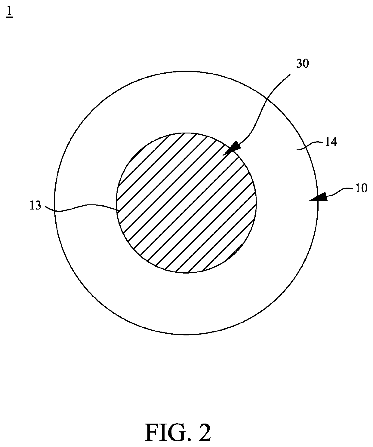
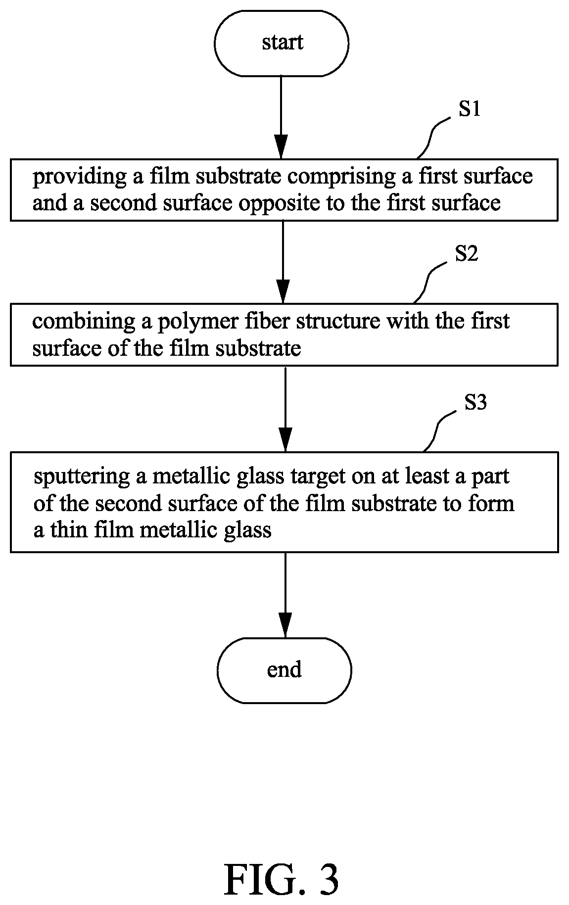
This patent describes a diaphragm structure that includes a film substrate, a polymer fiber structure, and a thin film metallic glass. The thin film metallic glass is formed on at least a part of the second surface of the film substrate using magnetron sputtering. The diaphragm structure has a rigidity of 34 N / m to 36 N / m and an absorbable energy of 23*10−12 joule to 44*10−12 joule. It also has a sound pressure level that is maintained within a range defined by a stable value±1 dB when an audio signal having a frequency of between 8 kHz and 10 kHz is outputted. The method of manufacturing the diaphragm structure involves combining a polymer fiber structure with the film substrate and sputtering a metallic glass target on at least a part of the second surface of the film substrate.

Problems solved by technology

An obvious disadvantage of this kind of diaphragm structure is that polymer materials are softer and thus have insufficient rigidity, such that sound distortion may occur when high-frequency sound signals are transmitted by the diaphragm structure.
However, as the thickness of the diaphragm structure increases, the frequency response of the diaphragm structure is affected, and the internal loss is additionally reduced by the metal plating layer such that the pitch is deteriorated.

Method used


Image

  • Diaphragm structure and method of manufacturing the same
  • Diaphragm structure and method of manufacturing the same
  • Diaphragm structure and method of manufacturing the same

Examples


Embodiment Construction

[0026]Since the various aspects and embodiments described herein are merely exemplary and not limiting, after reading this specification, skilled artisans will appreciate that other aspects and embodiments are possible without departing from the scope of the disclosure. Other features and benefits of any one or more of the embodiments will be apparent from the following detailed description and the claims.

[0027]The use of “a” or “an” is employed to describe elements and components described herein. This is done merely for convenience and to give a general sense of the scope of the invention. Accordingly, this description should be read to include one or at least one and the singular also includes the plural unless it is obvious that it is meant otherwise.

[0028]As used herein, the terms “first,”“second,” and the like are used for distinguishing between or referring to identical or similar elements or structures and not necessarily for describing a sequential or chronological order th...


PUM


Abstract

A diaphragm structure is used for an audio signal output device. The diaphragm structure includes a film substrate, a polymer fiber structure and a thin film metallic glass. The film substrate includes a first surface and a second surface opposite to the first surface. The polymer fiber structure is combined with the first surface of the film substrate. The thin film metallic glass is formed on at least a part of the second surface of the film substrate.

Description

CROSS-REFERENCE TO RELATED APPLICATION[0001]This application claims the priority benefits of Taiwan Patent Application No. 107129528, filed on Aug. 24, 2018, the entirety of which is hereby incorporated by reference herein and made a part of this specification.BACKGROUND OF THE INVENTION1. Field of the Invention[0002]The present disclosure generally relates to a diaphragm structure, and more particularly to a diaphragm structure combined with a metallic glass material. The present disclosure further comprises a method of manufacturing the diaphragm structure.2. Description of Related Art[0003]Generally, an audio output device such as a speaker or a headphone has a diaphragm structure inside. When sound signals are output, vibrations of the diaphragm structure are generated to transmit the sound. In order to generate effective vibration by the diaphragm structure with sound signals of different frequencies, the diaphragm structure is preferably made of a material having high rigidity...

Claims


Application Information

Patent Timeline
IPC IPC(8): H04R31/00H04R7/12
CPCH04R2307/023H04R7/127H04R2307/027H04R31/003H04R2307/025H04R7/125
Inventor CHU, JINN P.YU, CHIA-CHILAI, BO-ZHANGCHEN, CHUN-TAO
Owner NAT TAIWAN UNIV OF SCI & TECH
Learn More