
Device for drainage of the brain

a brain and brain technology, applied in medical science, bioelectric signal measurement, intracranial pressure measurement, etc., can solve the problems of significantly reducing patient comfort, headache and vomiting, congestion papillae, etc., and achieve the effect of reducing the comfort of patients' brain drainage devices

Active Publication Date: 2020-03-05
SNP SMART NEURO PROD GMBH
View PDF0 Cites 1 Cited by
  • Summary
  • Abstract
  • Description
  • Claims
  • Application Information

AI Technical Summary

Benefits of technology

The invention proposes a device for drainage of the brain through a hollow body with a sensor arrangement that can measure parameters of the brain mass. This device can be inserted through the cranium and into the brain to drain liquor from the ventricle while monitoring relevant physical parameters that reflect the patient's medical condition. The sensor arrangement is positioned in the brain mass and connected to a signal interface to transmit measurement data to a measuring system. The device is designed to be gentle and reliable while minimizing interference with the patient's body. The hollow body has a distal region with a thickening to gently push aside the cerebral mass. The material of the device is magnetically inactive to avoid interfering with imaging techniques such as MRIs.

Problems solved by technology

Increased intracranial pressure can, for example, lead to congestion papillae, headache and vomiting.
Conventional methods used to measure intracranial pressure are either non-invasive and thus offer a certain patient comfort with the respective measurement accuracy or invasive with a higher measurement of accuracy but significantly lower patient comfort.
If the CSF production is too high or if the CSF cannot drain properly because a tumour, cerebral haemorrhage or other swelling impairs drainage, this leads to the development of an internal hydrocephalus, a stasis of the cerebral water in the ventricular system.
This can put pressure on the brain (intracranial pressure), which can be life-threatening.

Method used


Image

  • Device for drainage of the brain
  • Device for drainage of the brain
  • Device for drainage of the brain

Examples


Embodiment Construction

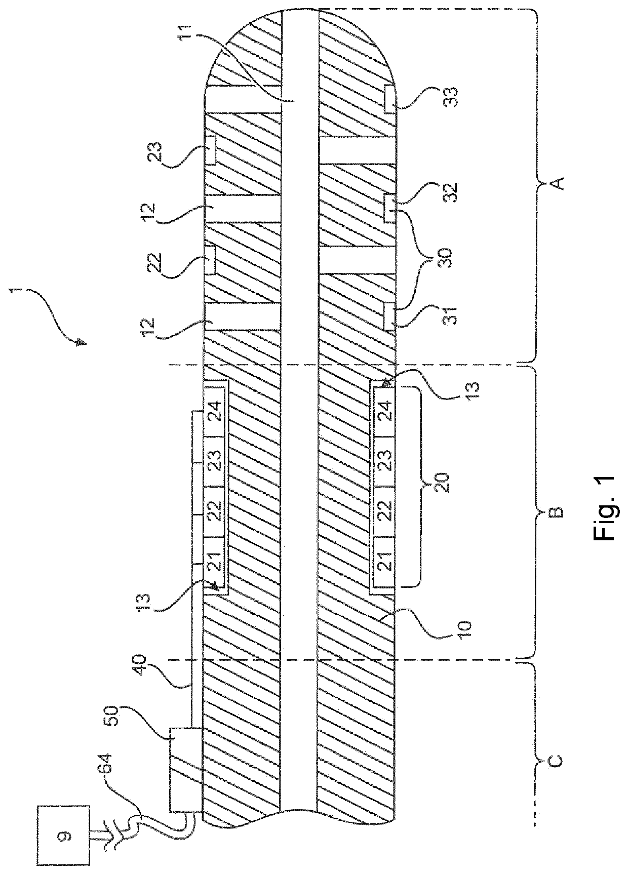
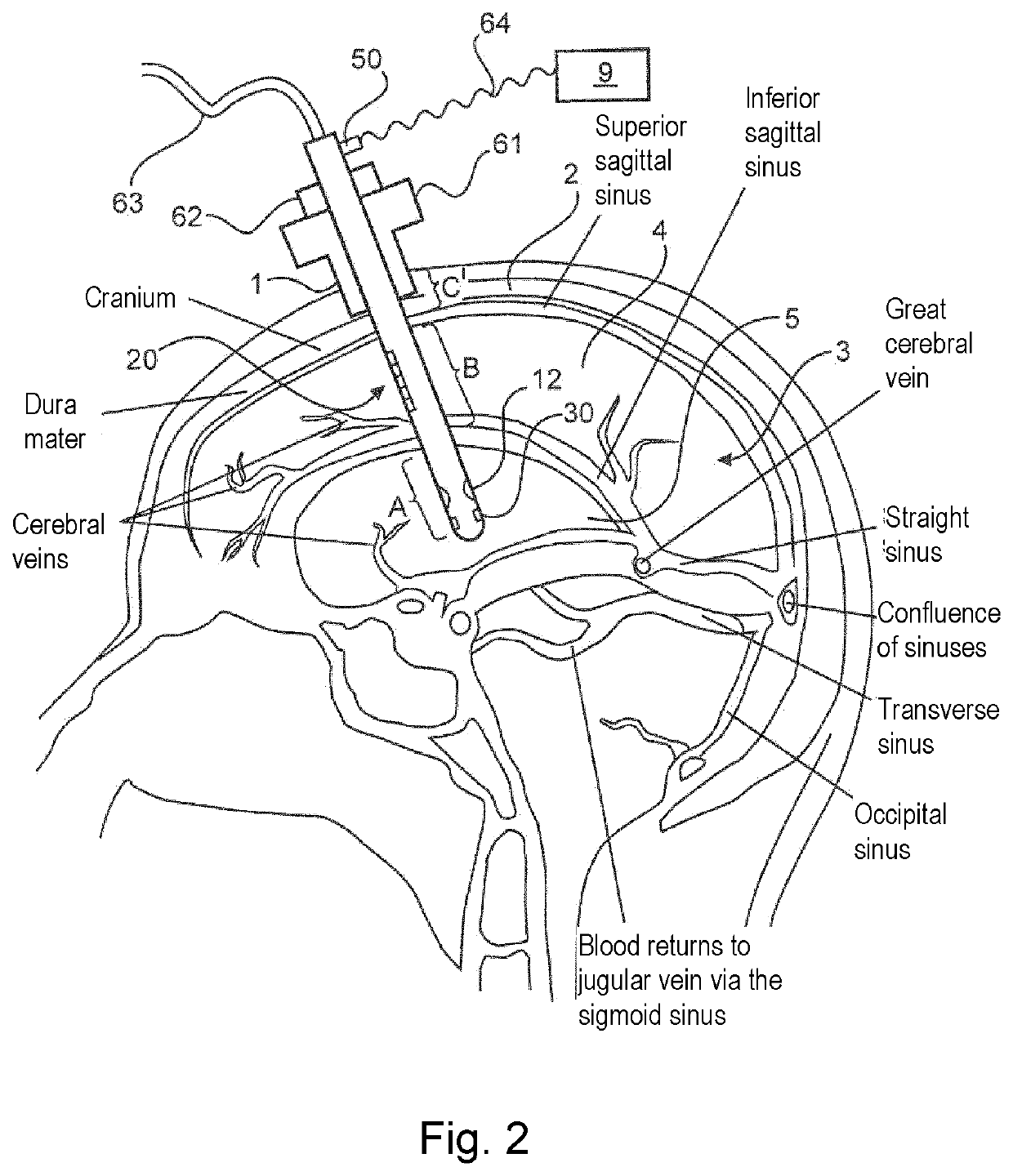
[0042]The present invention provides for a measurement directly on a probe of a device for drainage of the brain. In addition, the invention provides, inter alia, for the combination of several measurement methods (e.g. ICP (intracranial pressure measurement) via a probe, pressure measurement of the cerebral blood flow and measurement of brain activity, temperature, etc.) and the integration of ICP, blood flow measurement and brain activity in one device. Conventionally, such measuring methods take place independently of each other, and there is no aggregated data base from these measurements. Furthermore, known measuring methods suffer from the fact that the inaccuracy of the pressure measurement increases as the ICP becomes higher.

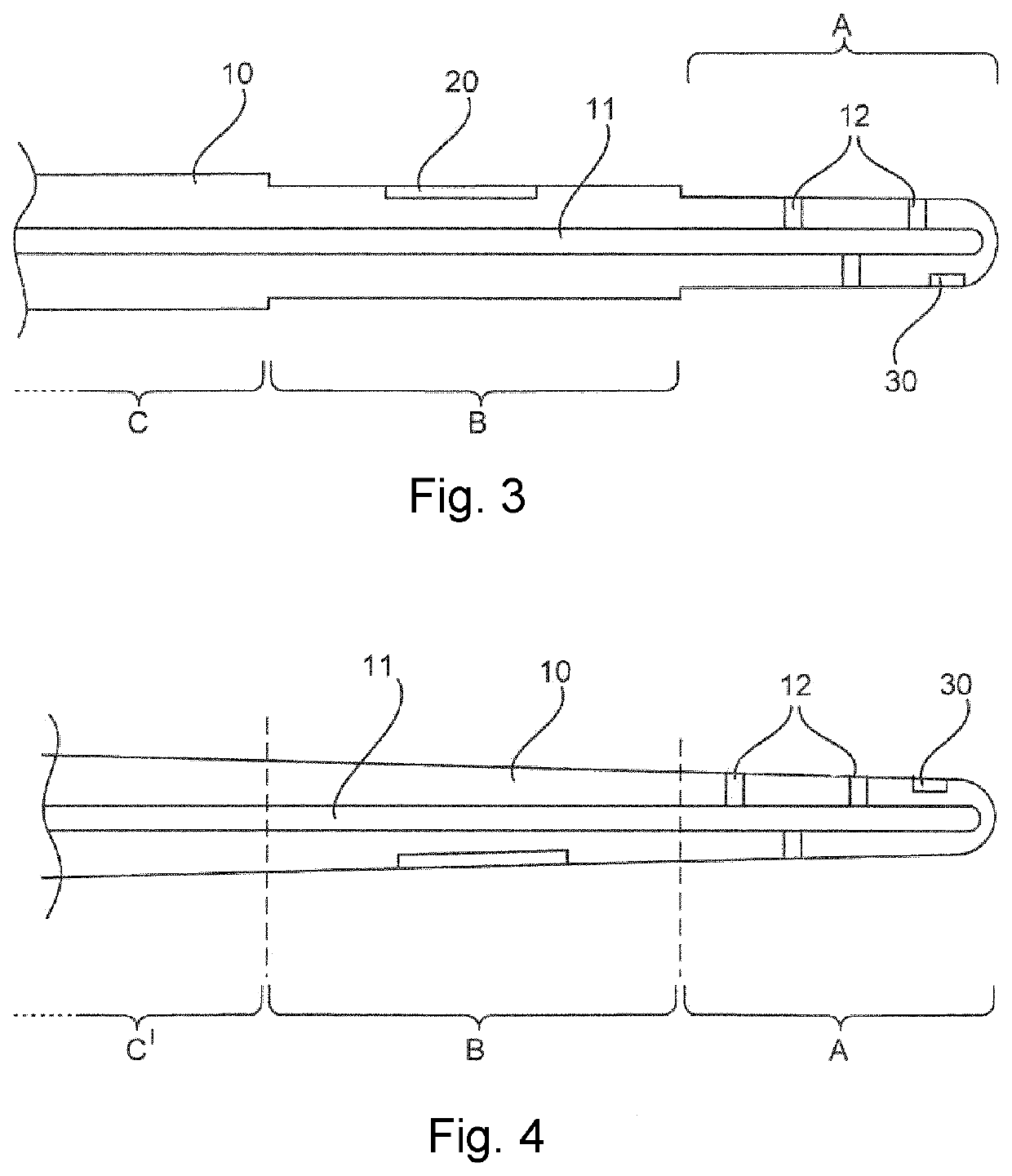
[0043]FIG. 1 shows an exemplary embodiment of the invention wherein the device for drainage of the brain 1 is shown in a cross-sectional view. The device for drainage of the brain has, for example, three regions: A, B, C. As can be seen in FIG. 2, the re...


PUM


Abstract

Brain drainage device having a rod-shaped hollow body (10) with an inner drainage channel (11) for insertion through the cranium into the brain, a first sensor arrangement (20) with at least one sensor (21, 22, 23, 24) for measuring a physical parameter, and a signal interface; wherein the rod-shaped hollow body has a first region A which, in the applied state, is designed to protrude into the ventricle situated in the brain; wherein the rod-shaped hollow body has a second region B, which is arranged proximally from the first region, wherein the second region is designed to lie in the region of the brain mass in the applied state; wherein the first sensor arrangement is arranged in the second region in order to measure a physical parameter of the brain mass; wherein the first sensor arrangement is connected to the signal interface such that measurement data determined by the first sensor arrangement are transmitted to a measuring system that is to be connected.

Description

CROSS-REFERENCE TO RELATED PATENT APPLICATION[0001]This application is a U.S. national stage entry of International Application PCT / EP2018 / 054316, filed Feb. 21, 2018, which claims priority to European Application 17157971.7, filed Feb. 24, 2017.TECHNICAL AREA[0002]The invention relates to a device for drainage of the brain, in particular a device for drainage of the brain with an integrated sensor arrangement for monitoring physical parameters, specifically the cerebral pressure during a procedure.BACKGROUND OF THE INVENTION[0003]Cerebral pressure is a colloquial term for the pressure that prevails inside the skull (intracranial pressure, commonly abbreviated as ICP in the medical field). The intracranial pressure is crucial for the circulation and thus for the functioning of the brain as it counteracts the pressure with which blood is pumped into the brain. If the intracranial pressure and mean arterial blood pressure are the same, the brain will no longer be supplied with blood. ...

Claims


Application Information

Patent Timeline
IPC IPC(8): A61B5/00A61B5/01A61B5/03A61B5/0478A61B5/1455A61M27/00
CPCA61B5/031A61B5/14551A61M27/006A61B5/6868A61B5/6864A61B5/0478A61B2562/12A61B5/01A61B5/6882A61B5/02055A61B5/14553A61B2505/05A61B5/293
Inventor LANGE, GEROEDER, HEINZROEDERER, CHRISTIAN
Owner SNP SMART NEURO PROD GMBH
Learn More