Subcutaneous tissue therapy treatment device

a treatment device and subcutaneous tissue technology, applied in the field of subcutaneous tissue therapy treatment devices, can solve the problems of imposing a large physical burden on the therapist, the inability of many therapists to have a uniform treatment technique,

Inactive Publication Date: 2020-03-05
IWAGAMI AKIHARU
View PDF0 Cites 1 Cited by
  • Summary
  • Abstract
  • Description
  • Claims
  • Application Information

AI Technical Summary

Benefits of technology

[0020]According to the invention described in claim 1, the bifurcated treatment portion is basically formed so as to perform the treatment which applies a pressing stimulus to an affected part while tracing a spherical surface of a cranial bone. Accordingly, a direction along which a largest pressing stress is applied to the cranial bone can be set to a direction perpendicular to a head of a patient in a face-down state. That is, in a state where the head of the patient in a standing posture is divided into four zones in a horizontal direction of the head and hence, a stimulus therapy can be applied to subcutaneous tissues in the four zones of the cranial bone ranging from a rear surface portion to a vertex region.
[0021]In the case where the cranial bone is divided into four zones ranging from the occipital region to the frontal region, a surface curved area which is a suboccipital muscles portion which covers a cranial base between left and right temporal bones in layers and is positioned between an inferior nuchal line of nuchal lines and a superior nuchal line of the nuchal lines is assumed as a first zone formed by dividing the surface of the cranial bone, a surface curved area which is an occipital muscle portion and an epicranial aponeurosis portion which cover a calvaria rear half portion between the left and right temporal bones and is defined by respective areas consisting of an area between the superior nuchal line of the nuchal lines and the frontal muscle and an area between the left and right temporal bones is assumed as a second zone formed by dividing the surface of the cranial bone, a surface curved area which is defined by a frontal muscle portion which covers a calvaria front half portion between the left and right temporal bones is a

Problems solved by technology

Accordingly, such a therapy has a drawback that it is impossible to ask many therapists to have a uniform therapeutic technique

Method used


Image

  • Subcutaneous tissue therapy treatment device
  • Subcutaneous tissue therapy treatment device
  • Subcutaneous tissue therapy treatment device

Examples


embodiment

1. Embodiment

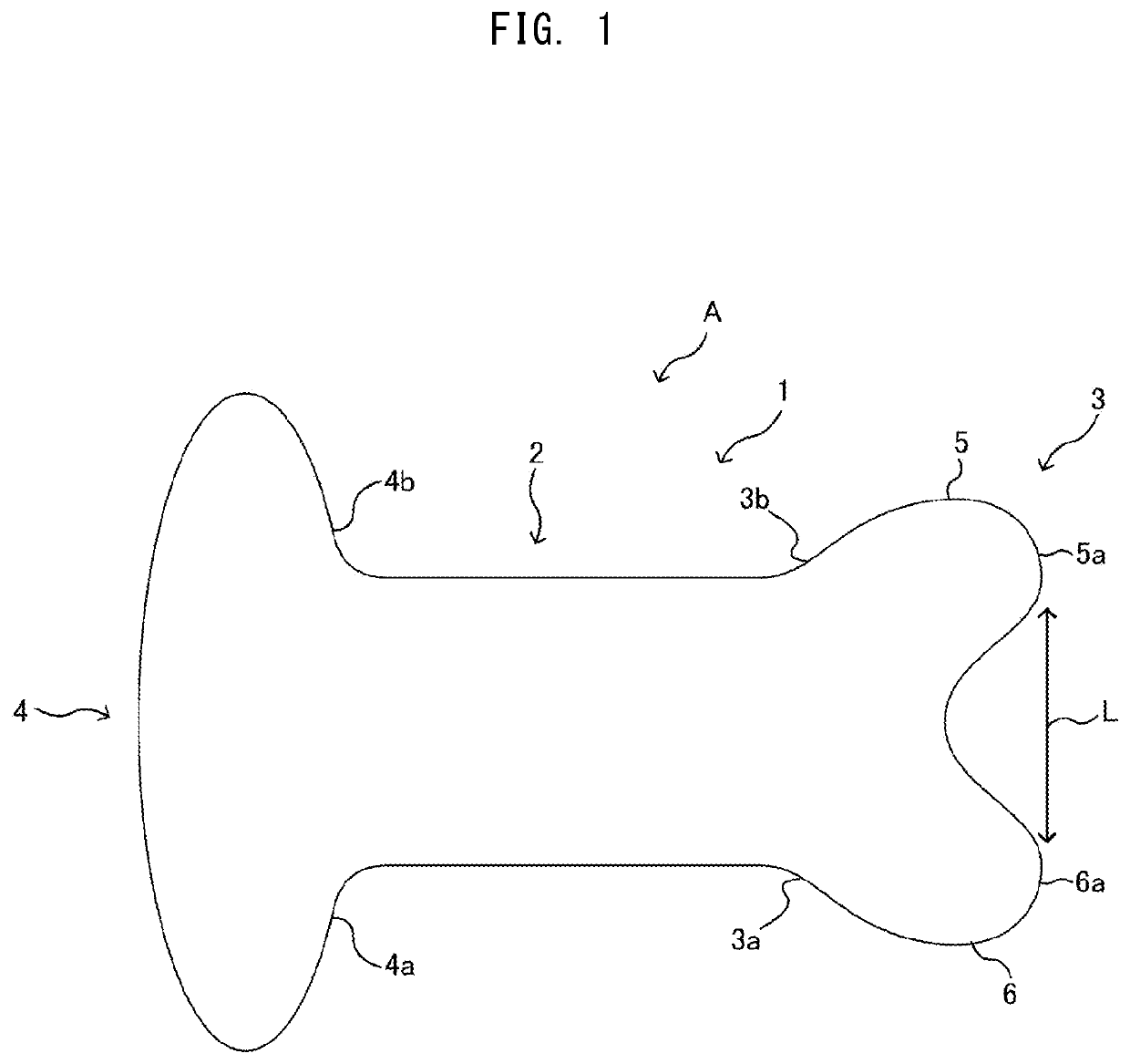
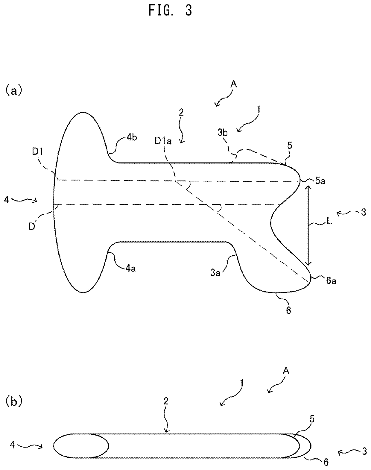
[0065]As shown in FIG. 1 and FIG. 3, a treatment device body 1 of a subcutaneous tissue therapy treatment device A according to this invention is formed of: a grip portion 2 having a rod shape or a narrow-width flat-plate shape; and a bifurcated treatment portion 3 for a neck and a head formed on a distal end of the grip portion 2; and a grasp portion 4 formed on a rear end of the grip portion 2.

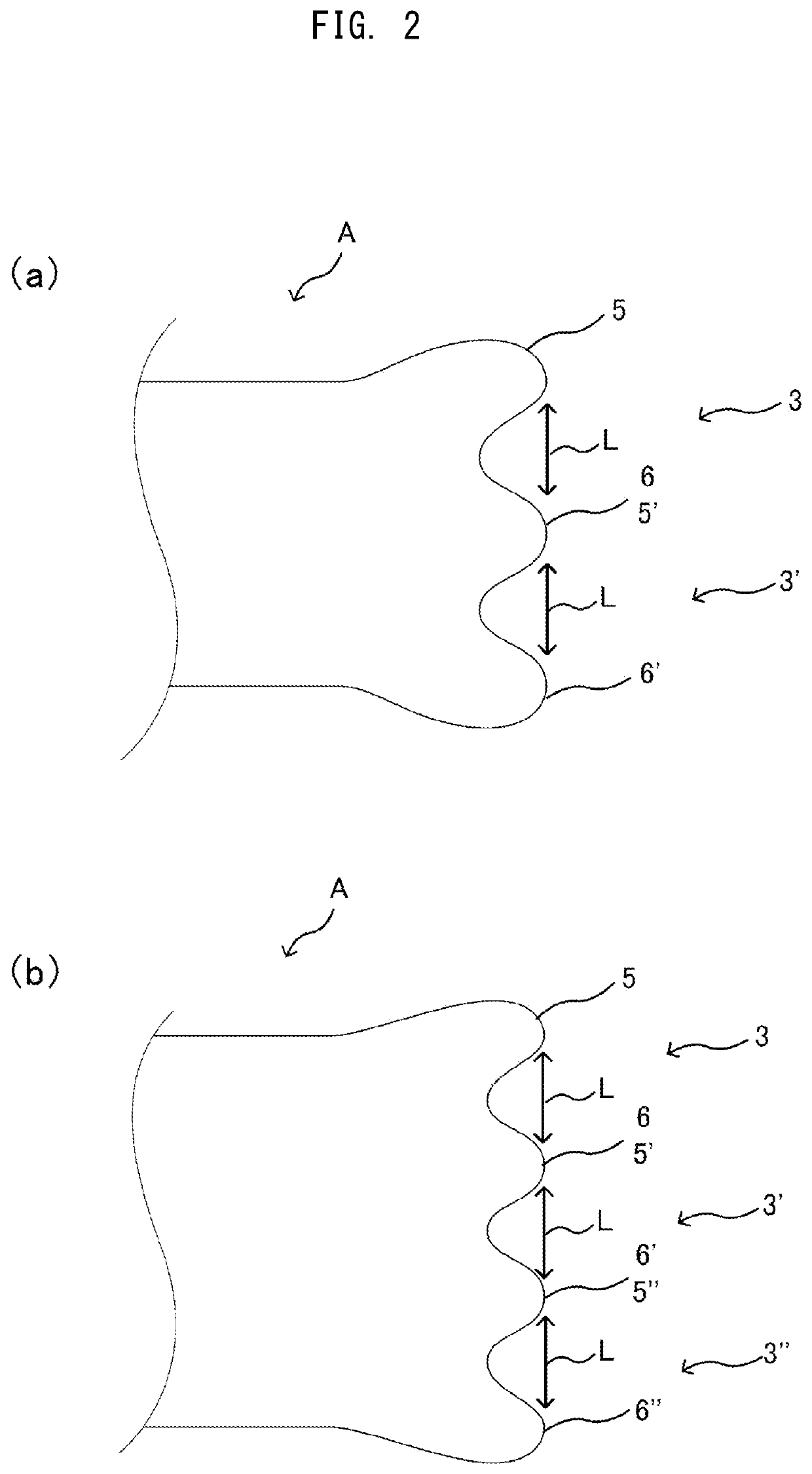
[0066]Further, in the treatment device body 1, the bifurcated treatment portion 3 for a neck and a head is formed of the combination of: a lower protrusion 6 positioned closer to the neck or a face portion during treatment; and an upper protrusion 5 positioned closer to a vertex region during treatment to each other. That is, the treatment device body 1 is formed in an approximately Y shape as shown in FIG. 1 and FIG. 3, a large wall thickness portion extending at a center portion of the Y shaped treatment device body 1 forms the grip portion 2, and a portion which extends from ...


PUM


Abstract

A subcutaneous tissue therapy treatment device is formed of: a rod-shaped grip portion; a bifurcated treatment portion for a neck and a head which is formed on a distal end of the grip portion; and a grasp portion which is formed on a rear end of the grip portion, and the bifurcated treatment portion for a neck and a head is formed by combining a lower protrusion positioned closer to the neck during treatment and an upper protrusion positioned closer to a vertex region during treatment to each other, an upper protrusion front end and a lower protrusion front end of the bifurcated treatment portion are formed with a distance which strides over meridians distributed in respective surface curved areas of respective zones in a case where a surface of a cranial bone is divided into four zones ranging from an occipital region to a frontal region.

Description

TECHNICAL FIELD[0001]The present invention relates to a subcutaneous tissue therapy treatment device capable of increasing immunity by applying a stimulus to subcutaneous tissues in four zones ranging from a neck to a frontal muscle or temporal muscles simply without requiring expertise by using a bifurcated treatment portion of the therapy treatment device for a neck and a head where a surface of a cranial bone ranging from the neck to the frontal muscle or the temporal muscles is divided into four zones with respect to an occipital bone, and the bifurcated treatment portion holds widths corresponding to widths of the respective zones.BACKGROUND ART[0002]Various kinds of muscles, nerves, and lymphatic vessels run through a part of a human body ranging from a neck to a frontal region or temporal muscles. Particularly, in an oriental medicine, meridians which connect scattered and concentrated acupuncture points (meridian points) to each other run through the part. Conventionally, ap...

Claims


Application Information

Patent Timeline
IPC IPC(8): A61H39/04
CPCA61H2205/021A61H39/04A61H2205/025A61H2201/0153A61H2201/1253A61H1/00A61H2205/04A61H2201/1695A61H2205/02A61H1/008A61H2201/1604
Inventor IWAGAMI, AKIHARU
Owner IWAGAMI AKIHARU
Why Eureka
Try Eureka