
Lamp with Elongated Housing

a technology of elongated housing and lamp, which is applied in the field of lighting, can solve the problem of not being able to provide a lens on the light source of a lamp with an elongated housing, and achieve the effects of convenient lens mounting, convenient assembly and disassembly, and convenient adjustment of the height of the housing

Active Publication Date: 2020-03-05
SELF ELECTRONICS CO LTD +2
View PDF7 Cites 1 Cited by
  • Summary
  • Abstract
  • Description
  • Claims
  • Application Information

AI Technical Summary

Benefits of technology

The present invention is a lamp with separate light-emitting units that have mounting holes in the housing. A fastening member is also present, making it easy to attach a lamp holder to each light source. This allows for the placement of a lens in each lamp holder, resulting in precise control over the beam angle and the creation of focused illumination. The invention also includes a limiting member that prevents wire sloshing and aims to improve the overall quality of the lamp.

Problems solved by technology

For a lamp with an elongated housing, since the lamp has a small mounting space in its width direction, making the mounting structure unable to be provided, and the elongated housing of the lamp is generally thin in wall thickness, making it impossible to provide the threaded mounting hole on the elongated housing of the lamp, it is generally impossible to provide a lens on the light source for a lamp with an elongated housing.
Therefore, for a lamp with an elongated housing, since there is no lens, the light emitted by the light source is dispersed, making it impossible to form light spot, so that a focused illumination cannot be formed on a certain area, and a certain area or an object cannot be under highlighted illumination.

Method used


Image

  • Lamp with Elongated Housing
  • Lamp with Elongated Housing
  • Lamp with Elongated Housing

Examples


Embodiment Construction

[0030]Embodiments of the invention are described in detail below, Examples of the embodiments are shown in the appended drawings in which consistently identical or similar labels represent identical or similar elements or elements having the same or similar function. The embodiments described below by reference to the drawings are exemplary and are only used for the interpretation of the invention and cannot be understood to be a limitation of the invention.

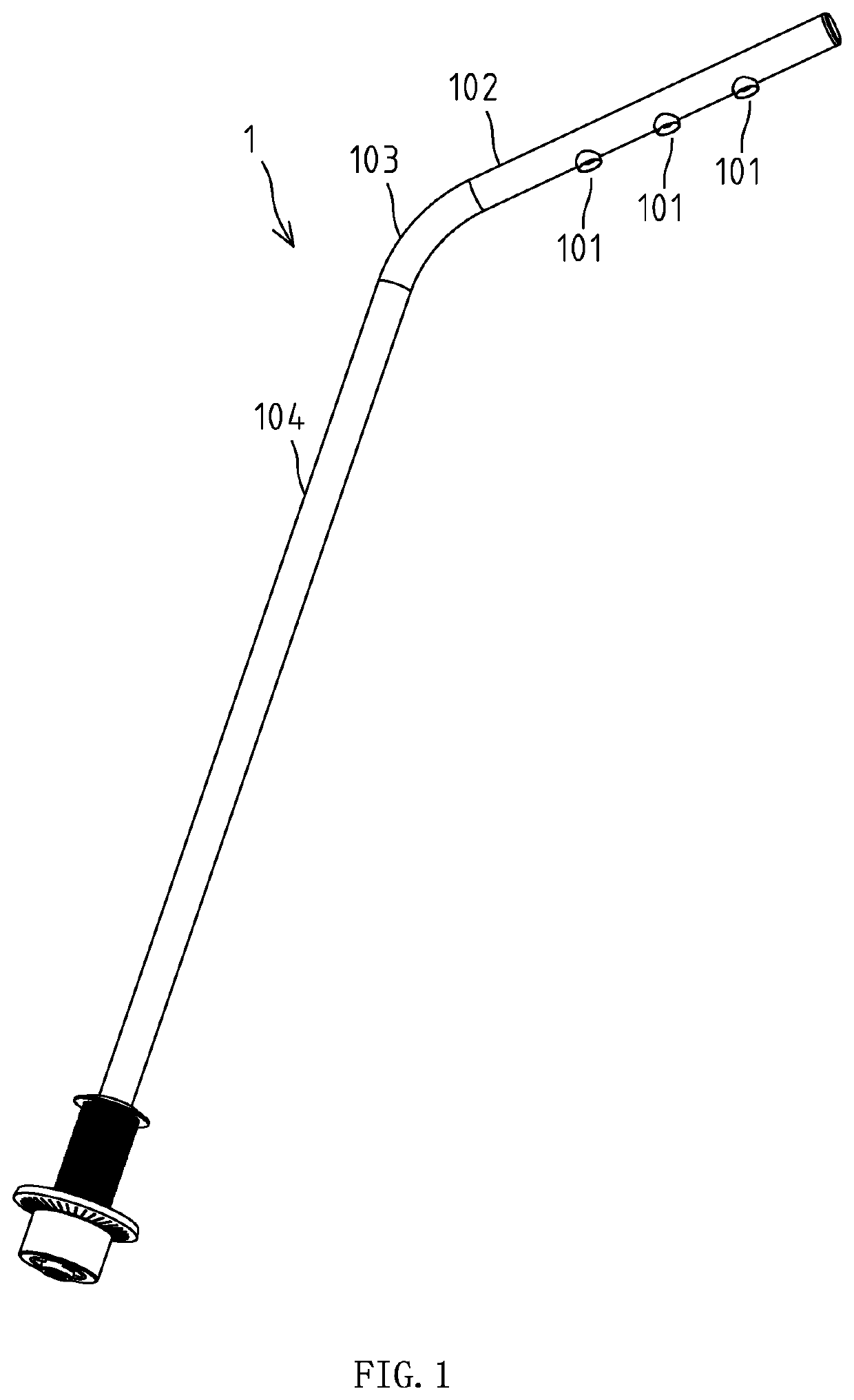
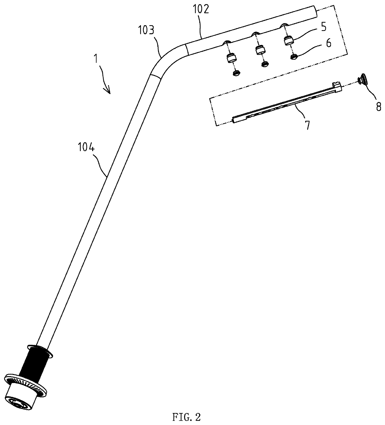
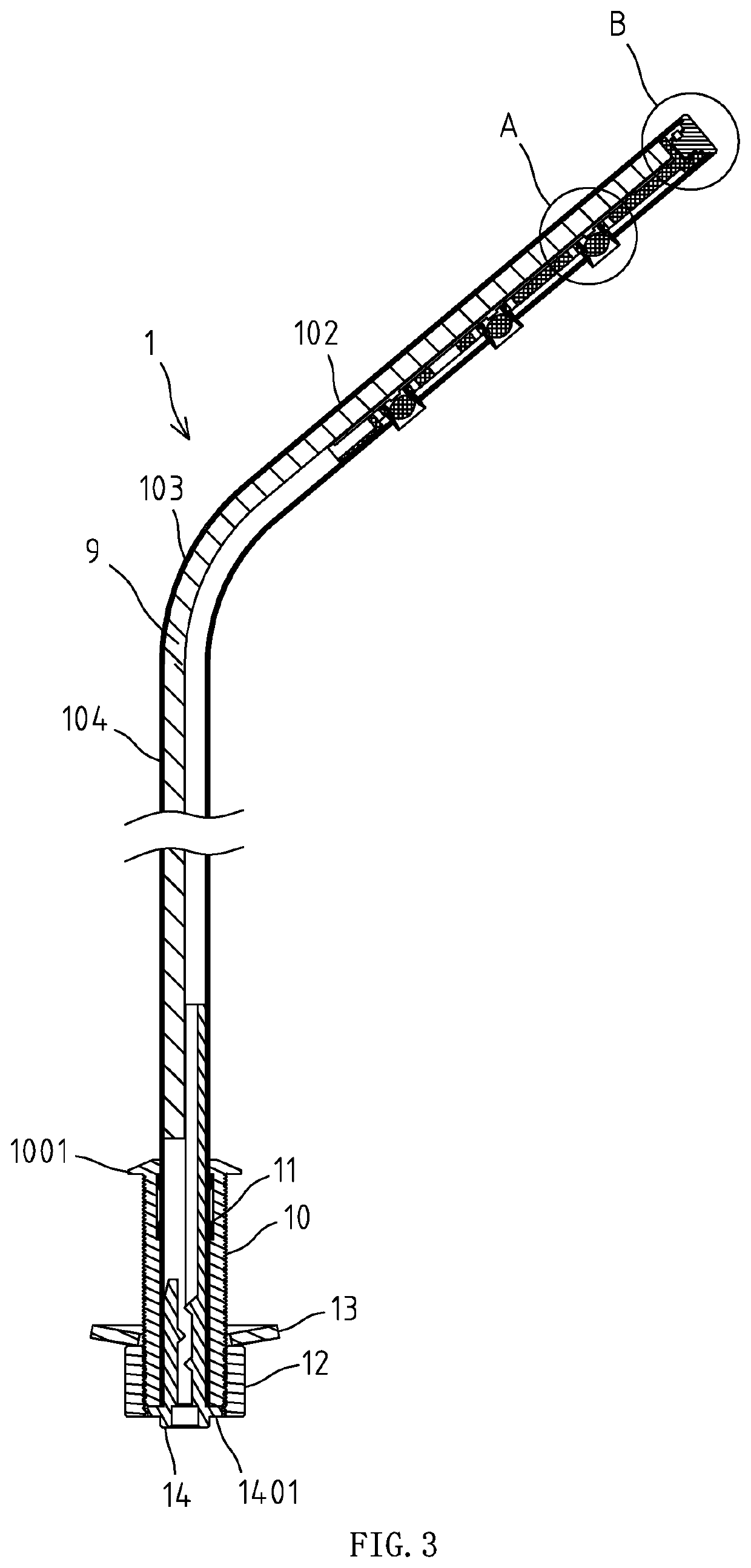
[0031]As shown in FIG. 1, FIG. 2 and FIG. 3, the lamp in the embodiment comprises an elongated housing 1 which is an elongated tubular member with a diameter of 0.5-1.5 cm. The housing 1 is provided with a bent part 103 which divides the housing 1 into two parts, one of which is a lamp pole part 104, and the other of which is a lamp head part 102. When the lamp is used, the lamp pole part 104 is vertically arranged, and the lamp head part 102 is inclined. There are three light-emitting units 101 on the lamp head part 102 and the ...


PUM

PropertyMeasurementUnit
lengthaaaaaaaaaa
areaaaaaaaaaaa
elastic clamping forceaaaaaaaaaa

Abstract

The invention relates to a lamp with elongated housing, comprising elongated housing and at least a light-emitting unit arranged on the housing; each of the light-emitting unit comprising: light source arranged in the housing; fastening member arranged in the housing; mounting hole arranged on the outer wall of the housing; lamp holder arranged in the mounting hole and fastened to the fastening member; lens arranged in the lamp holder. In the present invention, each light source can be provided with a lamp holder, and the light emitted by each light source can be emitted through the lens on the corresponding lamp holder, so that the beam angle of each light source can be controlled in a small range to form a light spot.

Description

RELATED APPLICATION[0001]This application claims priority to Chinese Patent Application No. CN 201811012837.2, filed on Aug. 31, 2018.FIELD OF THE TECHNOLOGY[0002]The present invention relates to lighting field, with particular emphasis on a lamp with elongated housing.BACKGROUND OF THE INVENTION[0003]For a lamp with an elongated housing, since the lamp has a small mounting space in its width direction, making the mounting structure unable to be provided, and the elongated housing of the lamp is generally thin in wall thickness, making it impossible to provide the threaded mounting hole on the elongated housing of the lamp, it is generally impossible to provide a lens on the light source for a lamp with an elongated housing. Therefore, for a lamp with an elongated housing, since there is no lens, the light emitted by the light source is dispersed, making it impossible to form light spot, so that a focused illumination cannot be formed on a certain area, and a certain area or an obje...

Claims


Application Information

Patent Timeline
Patent Type & Authority Applications(United States)
IPC IPC(8): F21V15/015F21S8/00F21V17/10F21V19/00F21V21/00
CPCF21V17/10F21V21/00F21V15/015F21V19/0015F21S8/00F21Y2115/10F21V15/01F21V29/70F21S8/08F21V5/04F21V17/005F21V17/164F21V19/003F21V19/0035F21V21/042F21Y2103/10
Inventor YANG, JUNDONG, JIANGUOXU, KAIHUANG, TONGHUA
Owner SELF ELECTRONICS CO LTD
Learn More