Lidar sensing device

a sensing device and lidar technology, applied in the field of lidar sensing devices, can solve the problems of increasing the number of parts, and achieve the effect of reducing the number of parts and improving the efficiency of light reception

Pending Publication Date: 2020-03-05
HYUNDAI MOBIS CO LTD
View PDF4 Cites 2 Cited by
  • Summary
  • Abstract
  • Description
  • Claims
  • Application Information

AI Technical Summary

Benefits of technology

[0011]Exemplary embodiments of the present invention provide a lidar sensing device capable of improving light reception efficiency and reducing the number of parts by removing a cover area.

Problems solved by technology

Accordingly, there is a problem in that the number of parts increases because the reflection mirror for bending an optical path is positioned in order to reduce the size of the lidar sensor.

Method used


Image

  • Lidar sensing device
  • Lidar sensing device
  • Lidar sensing device

Examples


first embodiment

[0031]First, a lidar sensing device according to the present disclosure will be described.

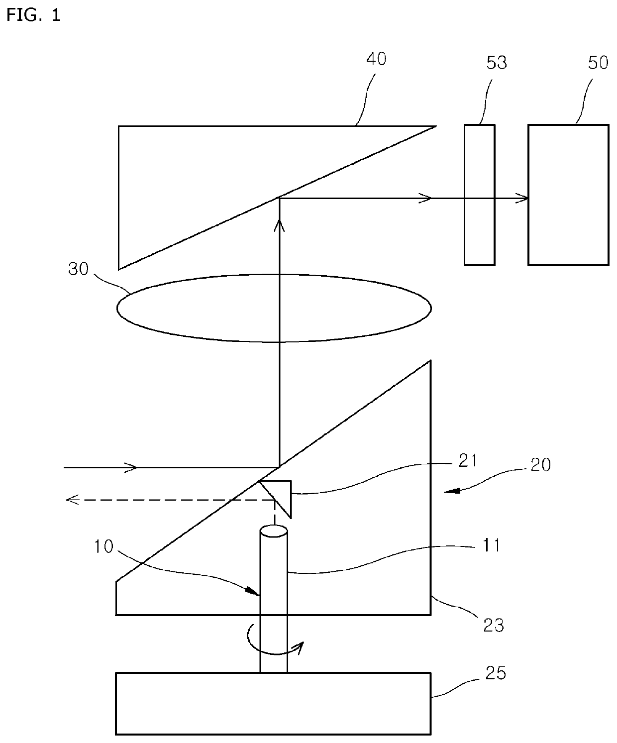
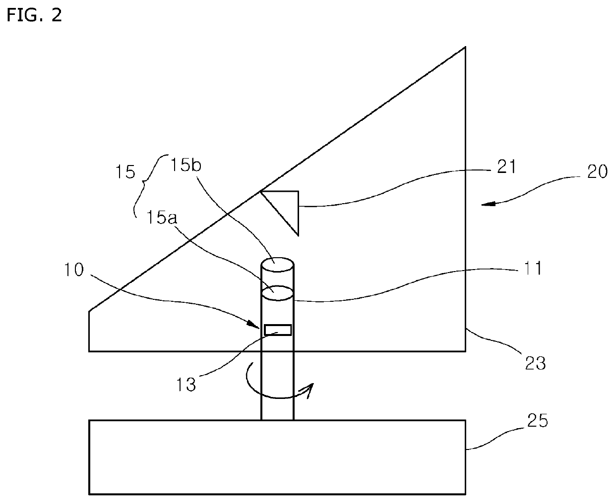
[0032]FIG. 1 illustrates the configuration of a lidar sensing device according to a first embodiment of the present disclosure. FIG. 2 illustrates the configuration of a sensing light source unit and a scanner unit in the lidar sensing device according to the first embodiment of the present disclosure.

[0033]Referring to FIGS. 1 and 2, the lidar sensing device according to the first embodiment of the present disclosure includes a sensing light source unit 10, a scanner unit 20, a light-receiving lens 30, a light-receiving reflector 40 and an optical detection unit 50.

[0034]The lidar sensing device includes a Tx-optical system and an Rx-optical system. The Tx-optical system includes a sensing light source unit 10 and a scanner unit 20. The Rx-optical system includes a light-receiving lens 30, a light-receiving reflector 40 and an optical detection unit 50. In FIG. 1, sensing light is indicated by...

second embodiment

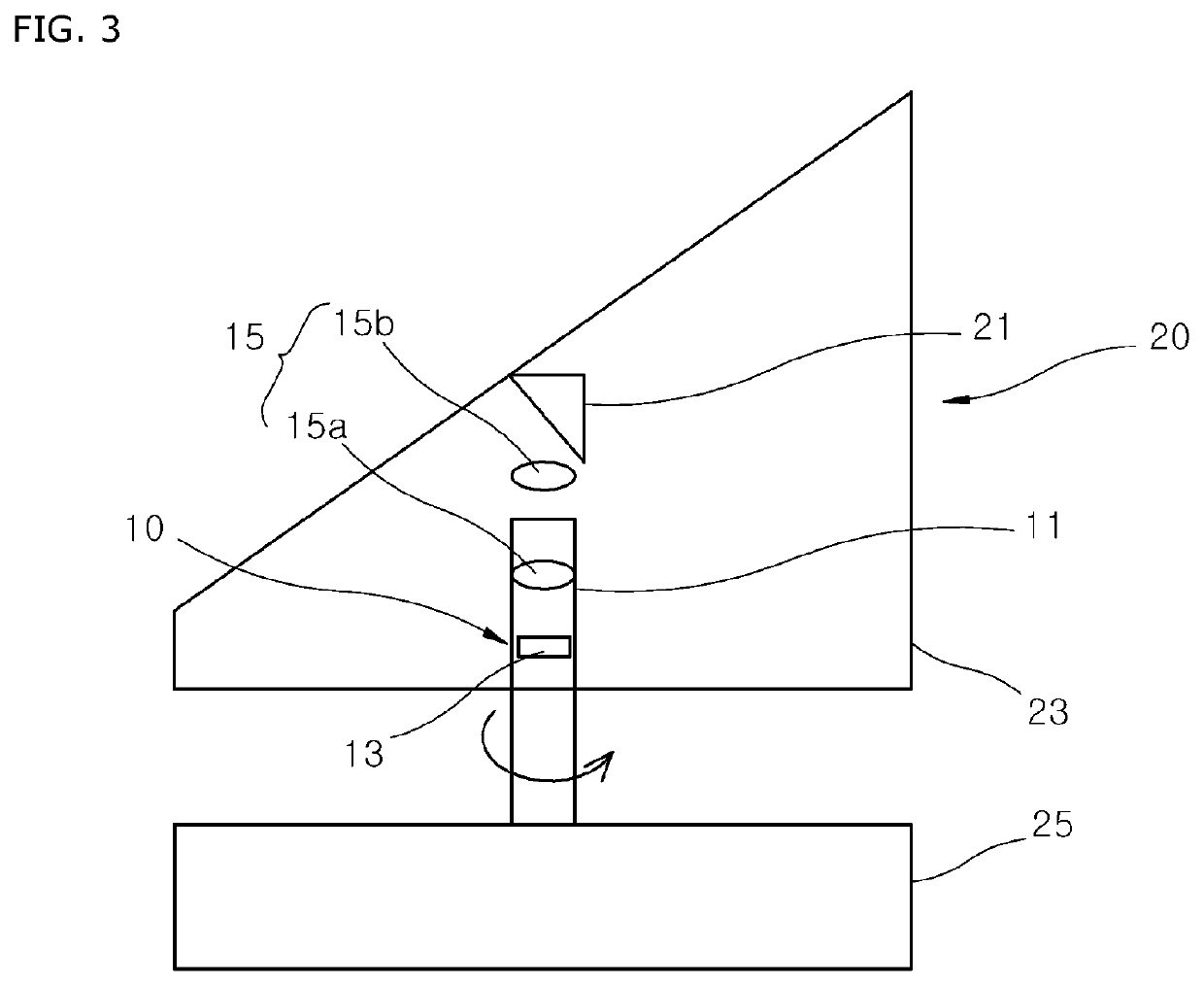
[0050]FIG. 3 illustrates the configuration of the sensing light source unit 10 and a scanner unit in the lidar sensing device according to the present disclosure.

[0051]Referring to FIG. 3, the sensing light source unit 10 of the lidar sensing device according to the second embodiment of the present disclosure includes a scope tube 11, a light source 13 and a light-transmitting lens unit 15.

[0052]The scope tube 11 may be formed in a cylindrical shape. The scope tube 11 prevents sensing light, radiated by the light source 13, from being spread to the surroundings.

[0053]The light source 13 is positioned within the scope tube 11. The light-transmitting lens unit 15 is positioned on the output side of the light source 13 so that sensing light radiated by the light source 13 is collimated. Output of sensing light can be improved because the light-transmitting lens unit 15 collimates the sensing light into a parallel beam.

[0054]The light-transmitting lens unit 15 includes a first light-tra...

third embodiment

[0057]A lidar sensing device according to the present disclosure will be described.

[0058]FIG. 4 illustrates the configuration of the lidar sensing device according to the third embodiment of the present disclosure. FIG. 5 illustrates the configuration of a sensing light source unit and a scanner unit in the lidar sensing device according to the third embodiment of the present disclosure.

[0059]Referring to FIGS. 4 and 5, the lidar sensing device according to the third embodiment of the present disclosure includes a sensing light source unit 10, a scanner unit 20, a light-receiving lens 30, a light-receiving reflector 40 and an optical detection unit 50.

[0060]The sensing light source unit 10 radiates sensing light. The sensing light source unit 10 includes a scope tube 11, a light source 13 and a light-transmitting lens unit 15.

[0061]The scope tube 11 may be formed in a cylindrical shape. The scope tube 11 prevents sensing light, radiated by the light source 13, from being spread to t...


PUM


Abstract

A light detection and ranging (“lidar”) sensing device including a sensing light source unit configured to radiate sensing light, a scanner unit configured to reflect the sensing light radiated by the sensing light source unit toward a target and to reflect incident light reflected by the target and integrated with the sensing light source unit, a light-receiving lens configured to transmit the incident light reflected by the scanner unit, a light-receiving reflector configured to reflect the incident light passing through the light-receiving lens, and an optical detection unit on which the incident light reflected by the light-receiving reflector is incident.

Description

CROSS-REFERENCE TO RELATED APPLICATION[0001]This application claims priority from the benefit of Korean Patent Application No. 10-2018-0105214, filed on Sep. 4, 2018, which is hereby incorporated by reference for all purposes as if set forth herein.BACKGROUNDField[0002]Exemplary embodiments of the present disclosure relates to light detection and ranging (“lidar”) sensing devices, and more particularly, to lidar sensing devices capable of improving light reception efficiency and reducing the number of parts by removing a cover area.Discussion of the Background[0003]With the development of the technology of a vehicle, a function, such as autonomous parking in addition to autonomous driving, is required. In order to perform such a function, the need of a lidar sensor is increased.[0004]The lidar sensor is mounted on the bumper of a vehicle, and detects a thing or structure by detecting the anterior and posterior of the vehicle. The lidar sensor is positioned within glass or the struct...

Claims


Application Information

Patent Timeline
Patent Type & Authority Applications(United States)
IPC IPC(8): G01S7/481
CPCG01S7/4817G01S7/4816G01S7/4814G01S17/02G01S17/931G01S17/42
Inventor KIM, WON GYUMJO, SUNG EUNKIM, KYUNG RINKIM, YOUNG SHIN
Owner HYUNDAI MOBIS CO LTD
Why Eureka
Try Eureka