Installation structure for vicinity information detection sensor

a technology of information detection and installation structure, which is applied in the direction of doors, using reradiation, instruments, etc., can solve the problems of vibration being damped by the elastic member and the vibration caused by so as to reduce the cost of installing the vicinity information detection sensor on the vehicle, curbed or prevented transmission of the operating noise of the motor to the interior of the vehicle cabin, and reduced wear between the outer panel and the retainer

Active Publication Date: 2020-03-05
TOYOTA JIDOSHA KK
View PDF12 Cites 1 Cited by
  • Summary
  • Abstract
  • Description
  • Claims
  • Application Information

AI Technical Summary

Benefits of technology

[0004]In some sensors for detecting vehicle vicinity information, a motor for changing the direction of radiation of radar waves may be installed. When the sensor equipped with the motor is used, there is room for improvement, in terms of prevention of transmission of operating noise of the motor to the interior of a vehicle cabin.
[0005]The disclosure provides an installation structure for a vicinity information detection sensor, which curbs transmission of operating noise of a motor to the interior of a vehicle cabin, in a vehicle in which the vicinity information detection sensor including the motor for changing the direction of radiation of radar waves is installed.

Problems solved by technology

With the vibration absorbing member thus placed between the outer panel and the vicinity information detection sensor, vibration caused by operating noise of the motor can be damped by the vibration absorbing member.
Thus, when vibration caused by operating noise of the motor is transmitted to the outer panel via a fastened portion of the vicinity information detection sensor and the retainer, the vibration is damped by the elastic member.

Method used


Image

  • Installation structure for vicinity information detection sensor
  • Installation structure for vicinity information detection sensor
  • Installation structure for vicinity information detection sensor

Examples


first embodiment

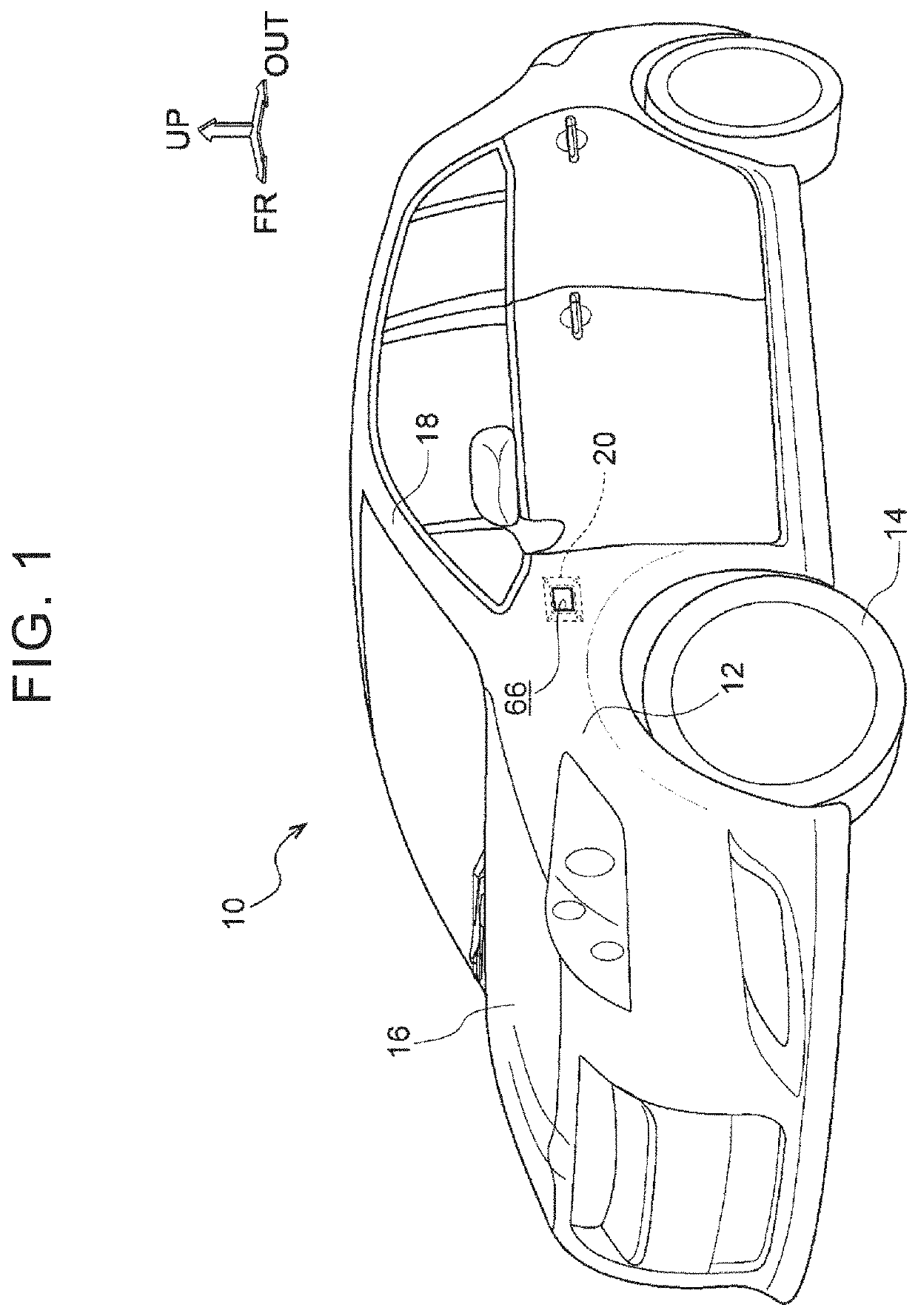
[0035]Referring to FIG. 1 through FIG. 7B, a vehicle 10 that employs an installation structure for a vicinity information detection sensor according to a first embodiment of the disclosure will be described. In FIG. 1, arrow FR indicates the vehicle front side of the vehicle on which the vicinity information detection sensor is mounted, and arrow UP indicates the vehicle upper side, while arrow OUT indicates the outer side in the vehicle width direction. When the longitudinal direction, vertical direction, and lateral direction are mentioned without being specified in the following description, they refer to the vehicle longitudinal direction, vehicle vertical direction, and vehicle lateral direction connecting the right and left sides when the viewer faces in the vehicle traveling direction, respectively.

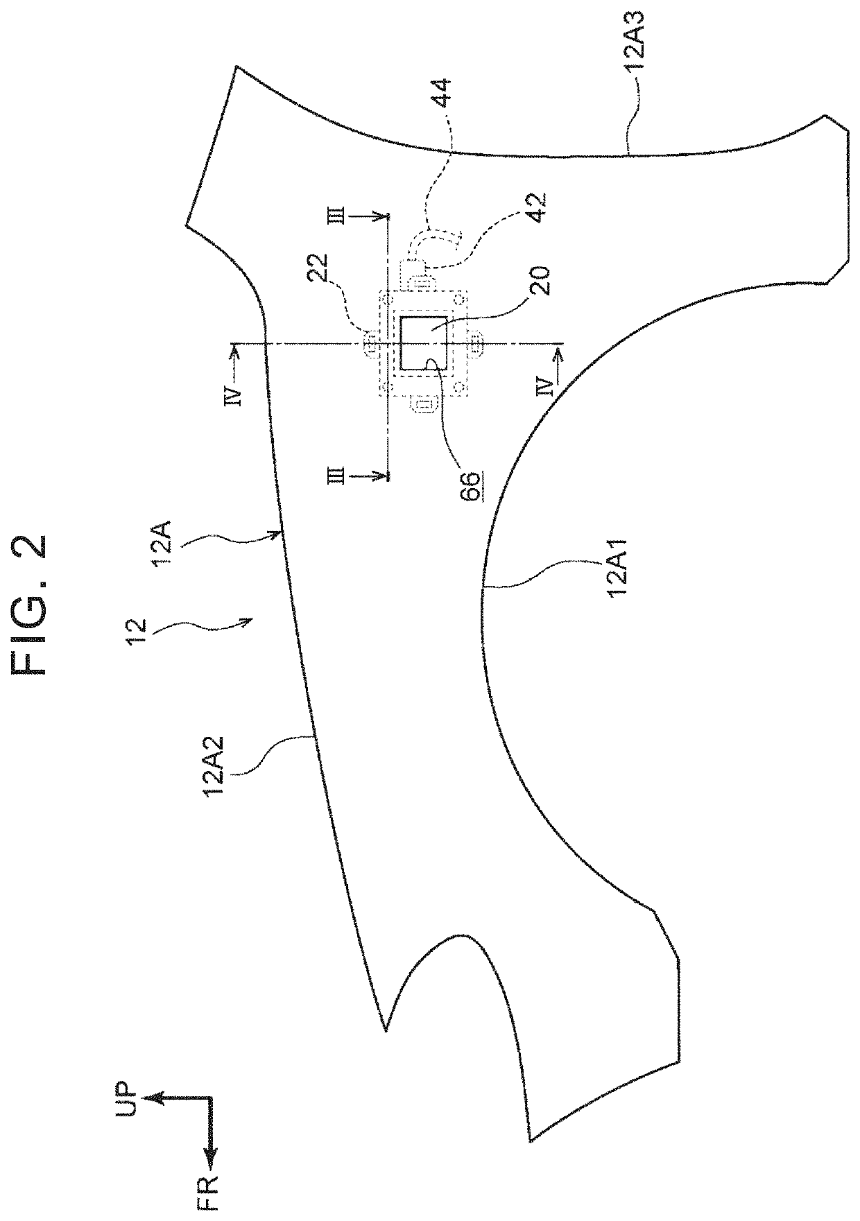
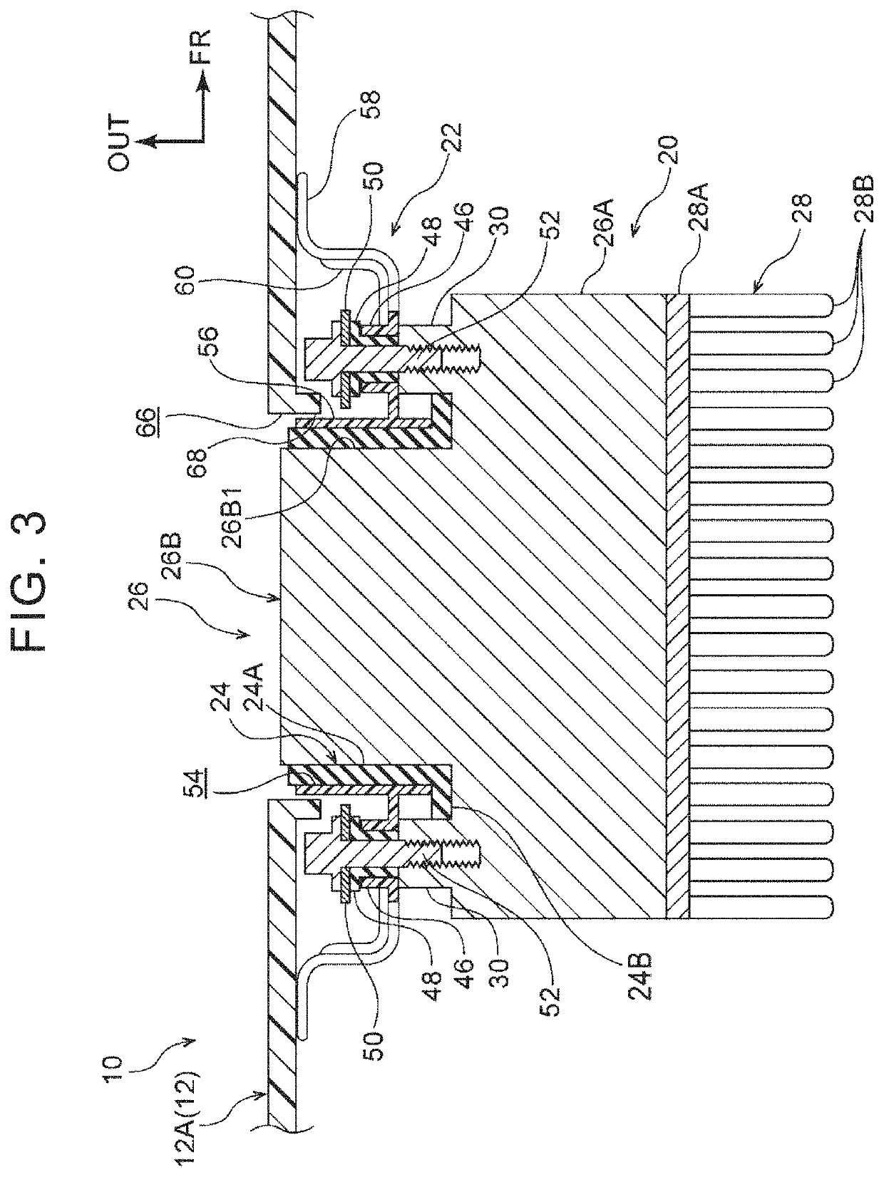
[0036]As shown in FIG. 1, a front fender panel 12 (which will be simply called “fender panel 12”) made of resin and serving as an outer panel of a vehicle body is placed on each of...

second embodiment

[0068]Referring next to FIG. 8 and FIG. 9, a vehicle 70 that employs an installation structure for a vicinity information detection sensor according to a second embodiment of the disclosure will be described. The same reference numerals are assigned to components similar to those of the first embodiment, and these components will not be further described.

[0069]As shown in FIG. 8, the vicinity information detection sensor 20 according to this embodiment is placed inside a front side door 72 of the vehicle 70.

[0070]The front side door 72 includes an inner door panel 74 and an outer door panel 76, and a front side window 78 is placed between the inner door panel 74 and the outer door panel 76.

[0071]The inner door panel 74 is located on the vehicle inner side, and provides an inner panel of the front side door 72, and an inner belt-line reinforcement 80 (which will be simply called “inner RF 80”) is placed on the vehicle outer side of an upper end portion of the inner door panel 74. The...

third embodiment

[0077]Referring next to FIG. 10 and FIG. 11, a vehicle 90 that employs an installation structure for a vicinity information detection sensor according to a third embodiment of the disclosure will be described. The same reference numerals are assigned to components similar to those of the first embodiment, and these components will not be further described.

[0078]As shown in FIG. 10, the vicinity information detection sensor 20 according to this embodiment is placed in the upper part of the front pillar 18 of the vehicle 90. More specifically, the vicinity information detection sensor 20 is placed on the vehicle inner side of a pillar garnish 99 (which will be simply called “garnish 99”) that serves as an outer panel of the vehicle body, and provides a design surface of the front pillar 18 having a closed cross-section structure.

[0079]As shown in FIG. 11, the front pillar 18 includes an inner pillar panel 92 and an outer pillar panel 94. The inner pillar panel 92 is located on the veh...


PUM


Abstract

An installation structure for a vicinity information detection sensor includes the vicinity information detection sensor and a vibration absorbing member. The vicinity information detection sensor includes a detector attached to a vehicle inner side of an outer panel of a vehicle body and configured to radiate electromagnetic waves that function as radar waves that detect vicinity information of a vehicle, and a motor provided in the detector and configured to change a radiation direction of the electromagnetic waves. The vibration absorbing member is placed between the outer panel and the vicinity information detection sensor.

Description

INCORPORATION BY REFERENCE[0001]The disclosure of Japanese Patent Application No. 2018-159175 filed on Aug. 28, 2018 including the specification, drawings and abstract is incorporated herein by reference in its entirety.BACKGROUND1. Technical Field[0002]The disclosure relates to an installation structure for a vicinity information detection sensor.2. Description of Related Art[0003]In a structure disclosed in Japanese Unexamined Patent Application Publication No. 2016-179752 (JP 2016-179752 A), a vicinity information detection sensor having a millimeter-wave radar for detecting vicinity information of a vehicle is installed on a framework member (vehicle constituent member) of the vehicle. According to the related art, the vicinity information detection sensor is attached to the framework member of the vehicle, using fasteners, such as bolts,SUMMARY[0004]In some sensors for detecting vehicle vicinity information, a motor for changing the direction of radiation of radar waves may be ...

Claims


Application Information

Patent Timeline
Patent Type & Authority Applications(United States)
IPC IPC(8): G01S13/93G01S13/04G01S7/03B60J5/04
CPCB62D29/043B60J5/042B60J5/0468G01S2013/93274G01S7/03G01S13/04G01S13/931B60J5/0481B60R11/02G01S7/02G01S7/4813G01S2013/93275G01S2013/93272G01S2013/93271G01S17/931G01S7/027
Inventor ASO, SHUICHI
Owner TOYOTA JIDOSHA KK
Why Eureka
Try Eureka