Connector device

a technology of connecting rods and connectors, applied in the direction of electrical devices, coupling device connections, transportation and packaging, etc., can solve the problems of generating likely second terminal wear and and achieve the effect of reducing the wear of the first terminal

Active Publication Date: 2020-03-05
YAZAKI CORP
View PDF21 Cites 0 Cited by
  • Summary
  • Abstract
  • Description
  • Claims
  • Application Information

AI Technical Summary

Benefits of technology

The present invention aims to provide a connector device that reduces wear and tear on the first and second terminals. This is achieved by configuring the second terminals with contact points that slide on a guide surface of a resin cover body, reducing the distance between the contact points and the first terminals, and preventing wear and tear on the second terminal. Additionally, the cover body may overlap the first terminals or include an insulating member, further reducing wear and tear on the second terminal. The second terminal may also have arms that make it easy to sandwich the first terminals. Overall, this invention simplifies connector device configuration and reduces costs.

Problems solved by technology

Thus, there has been the problem that wear of the first terminals and the second terminal is likely to be generated.

Method used


Image

  • Connector device
  • Connector device
  • Connector device

Examples


Embodiment Construction

[0016]An embodiment according to the present invention will now be described in detail with reference to the accompanying drawings. It should be noted that this embodiment is not intended to limit this invention. Components in the embodiment include components that can be replaced and are facilitated by the skilled person or substantially like components.

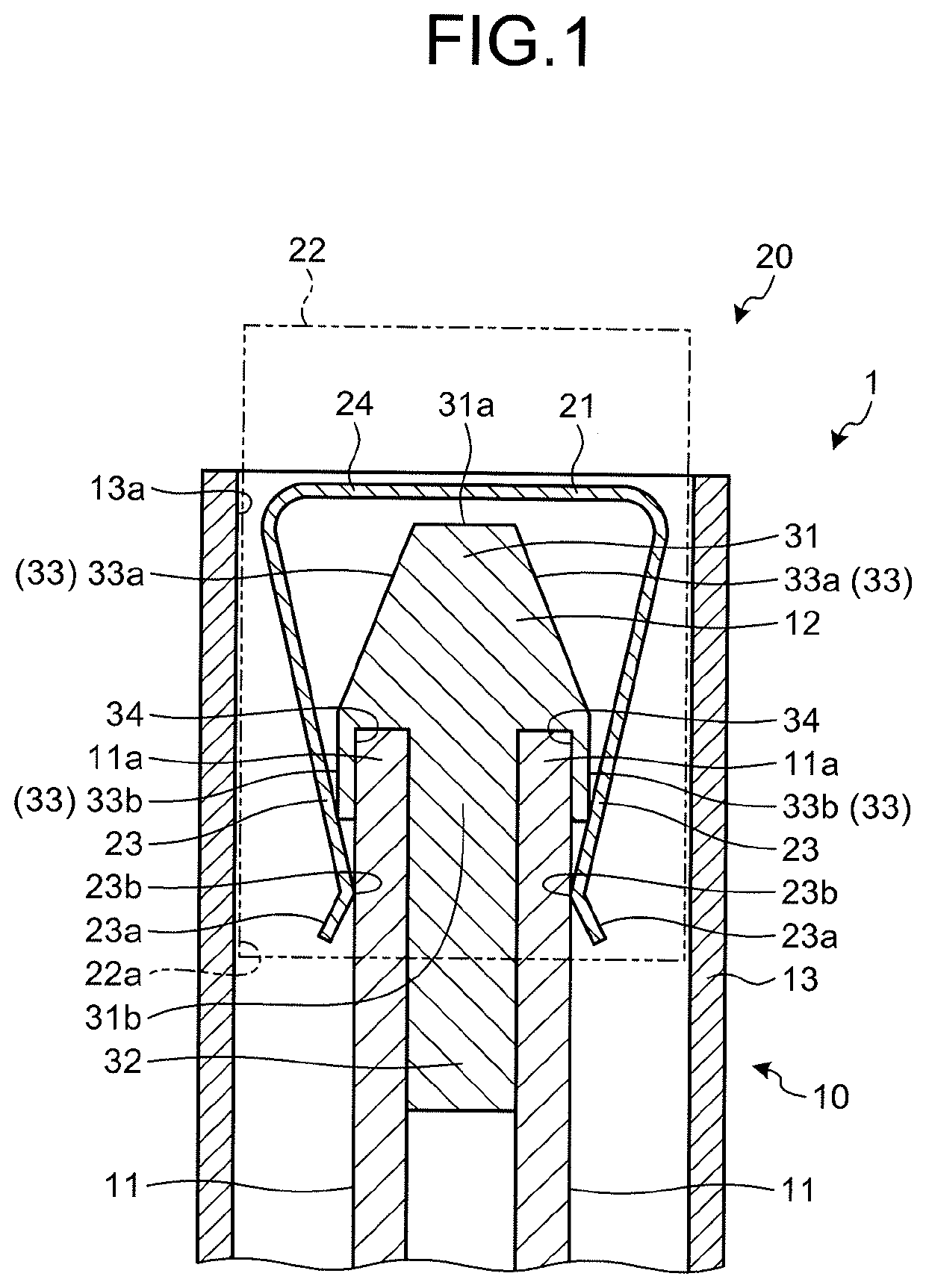
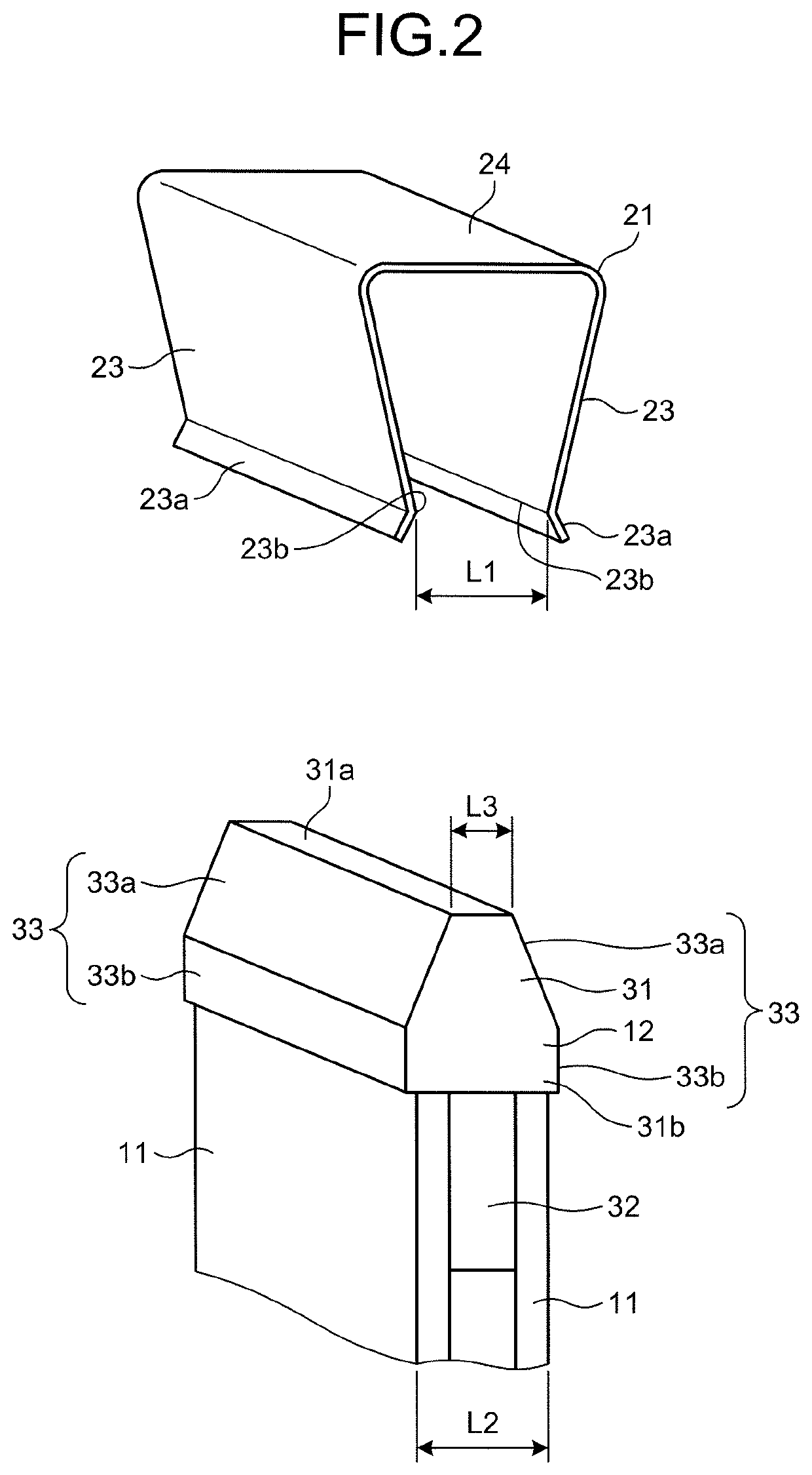
[0017]FIG. 1 is a cross-sectional view of a connector device according to the present embodiment. FIG. 2 is an exploded perspective view illustrating first terminals and a second terminal included in the connector device. The connector device according to the present embodiment is provided to, for example, a connecting part of a service plug that is mounted on vehicles including an electric vehicle and a hybrid vehicle. This kind of service plug is incorporated in a power source circuit for supplying power from a power source unit such as a battery to a load unit such as a rotating electrical machine, and is a device that causes thi...


PUM


Abstract

A connector device includes a pair of first terminals, a second terminal, and a cover body. The first terminals are arranged in parallel. The second terminal includes a pair of contact points that are electrically connected to the respective first terminals, and is biased by a spring so that the contact points collectively sandwich the first terminals. The cover body made of a resin is attached to tip parts of the first terminals. The cover body includes first guide surfaces that have the contact points of the second terminal sliding thereon and guide the contact points in a direction for separating the contact points when the first terminals are connected to the second terminal. Thus, wear of the first terminals and the second terminal can be reduced.

Description

CROSS-REFERENCE TO RELATED APPLICATION[0001]This application is a continuation application of International Application No. PCT / JP2018 / 004251 filed on Feb. 7, 2018 which claims the benefit of priority from Japanese Patent Application No. 2017-114124 filed on Jun. 9, 2017 and designating the U.S., the entire contents of which are incorporated herein by reference.BACKGROUND OF THE INVENTION1. Field of the Invention[0002]The present invention relates to a connector device that includes a second terminal sandwiching a pair of first terminals and being connected to the first terminals.2. Description of the Related Art[0003]Conventionally, there has been known a service plug (power source circuit breaking device) that is mounted on vehicles including mainly an electric vehicle and a hybrid vehicle, is incorporated in a power source circuit for supplying power from a power source unit such as a battery to a load unit such as a rotating electrical machine, and can connect or block this powe...

Claims


Application Information

Patent Timeline
Patent Type & Authority Applications(United States)
IPC IPC(8): H01R13/04H01R13/66H01R13/187H01R12/70
CPCH01R12/7005H01R13/04H01R13/66H01R13/187B60L3/04B60L53/16H01H9/085H01R31/08Y02T10/70Y02T10/7072Y02T90/14
Inventor MOTOSHIGE, YUICHI
Owner YAZAKI CORP
Why Eureka
Try Eureka