

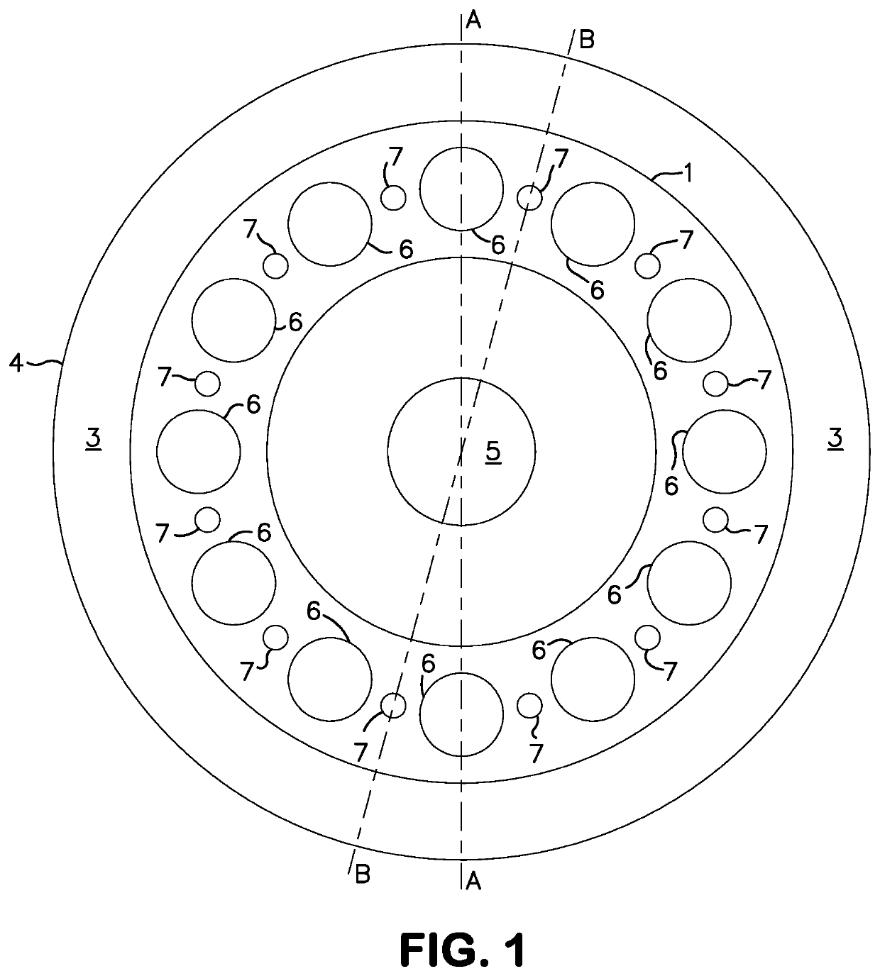
Fluidic burner with heat stability
a burner and flue gas technology, applied in the field of burners, can solve problems such as overheating of the burner nozzle, and risks of encountering operational drawbacks
- Summary
- Abstract
- Description
- Claims
- Application Information
AI Technical Summary
Benefits of technology
Problems solved by technology
Method used
Image

Examples
examples
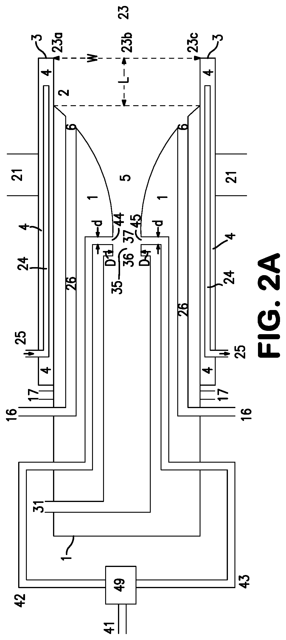
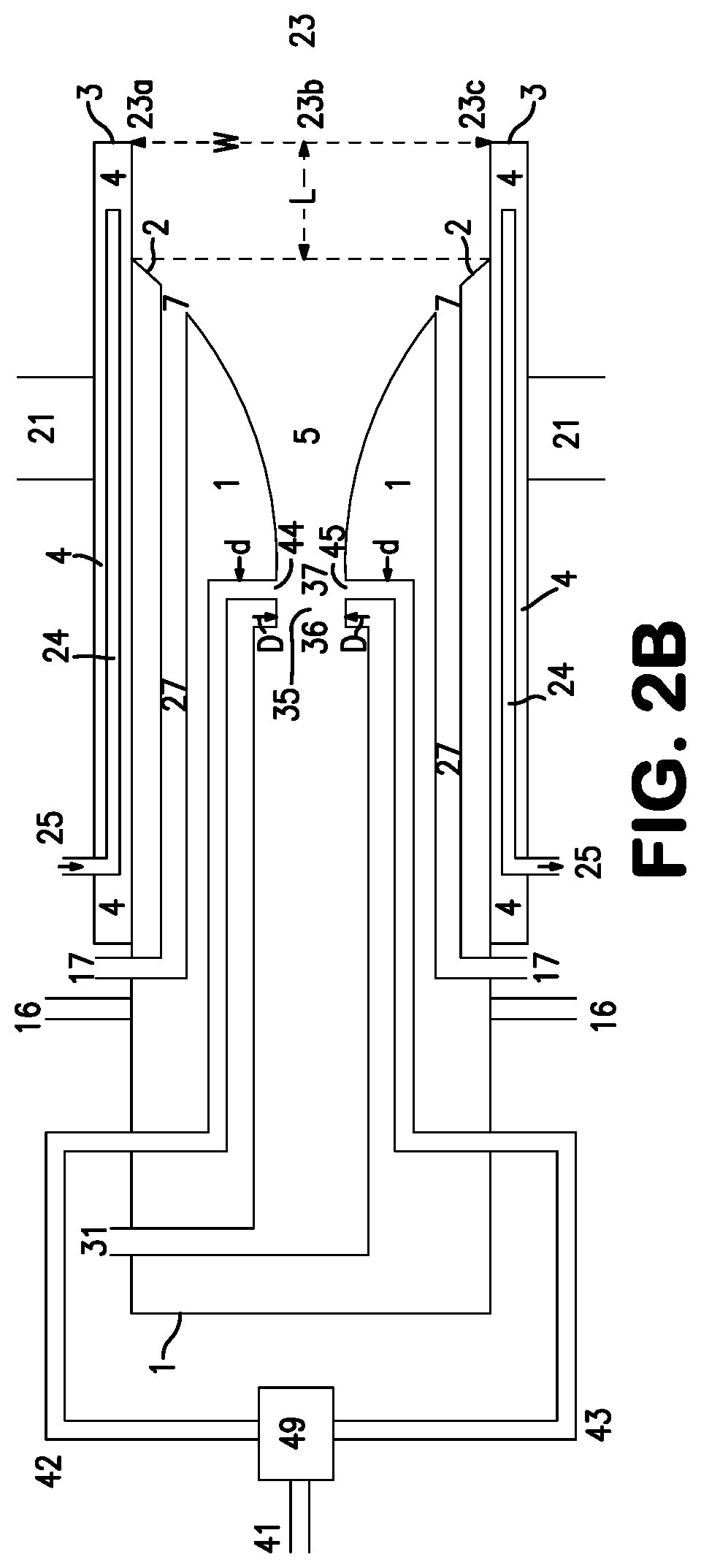
[0051]Burners as described herein were made and tested. One burner had a nominal design firing rate of 3 MW and the other had a nominal firing rate of 5 MW. Relevant dimensions of each of these burners are set forth in the following table:
DiameterD ofrestrictedBiasing gasRatio ofNo. offlow areaNumberFiringLength ofpassagewaybiasing gasNumbernatural(fluidicofTotalratecentraldiameter dpassagewayof O2gascavity)biasingNozzle(MW)passageway*(inches)diameter d to Dportsports(inches)portslength32D0.1560.2880.853-42D53D0.1880.1812120.853-43D*The length of the central passageway is measured from the point of communication of the central passageway with the fluidic cavity to the downstream end of the central passageway.
The burners were operated at the conditions that are set forth in the following table:
Velocity BurnerMain 02Shroud 02Shroud NGBias flow(feet per sec)- firing rate(scfh)(scfh)(scfh)(scfh)Bias flow3 MW122408160102005006605 MW204001360017000500 and900greater
These burners can be ope...
PUM
| Property | Measurement | Unit |
|---|---|---|
| angle | aaaaa | aaaaa |
| velocity | aaaaa | aaaaa |
| velocity | aaaaa | aaaaa |
Abstract
Description
Claims
Application Information