Eyecups for optics

a technology of eyecups and optics, applied in the field of optics, can solve the problems of difficult to maintain a specified switching distance that allows traditional eyecups to function, undesirable light emission from devices,

Active Publication Date: 2020-03-12
SENSORS UNLTD
View PDF12 Cites 4 Cited by
  • Summary
  • Abstract
  • Description
  • Claims
  • Application Information

AI Technical Summary

Benefits of technology

[0005]The eyecup can include one or more magnets disposed on at least one of the one or more flaps to move with the one or more flaps, and one or more sensors disposed in a fixed location (e.g., relative to the portion of the eyecup that is fixed relative to the optic), e.g., such as on or in the elastic body, and configured to sense a magnetic ...

Problems solved by technology

However, in some cases emission of the light from the device is not desirable.
The magnetic flux density changes with temperature and magnets ...

Method used


Image

  • Eyecups for optics
  • Eyecups for optics
  • Eyecups for optics

Examples


Embodiment Construction

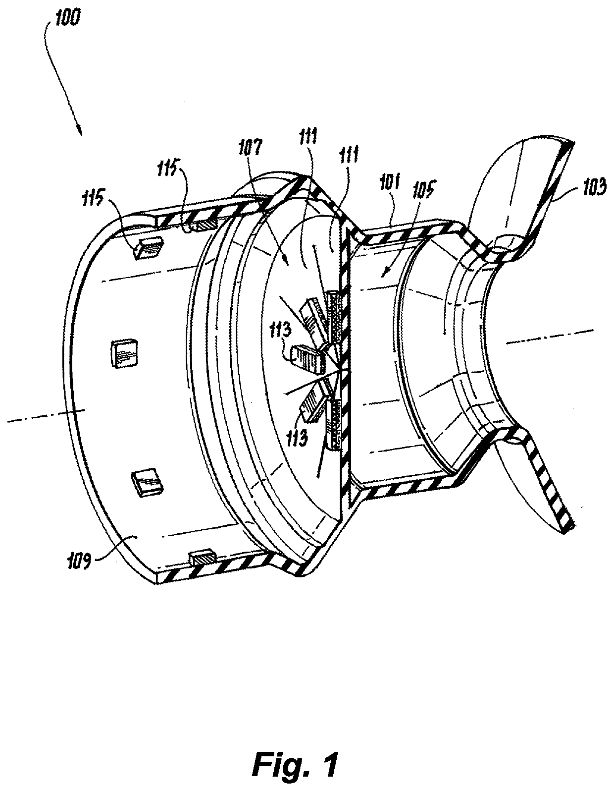
[0018]Reference will now be made to the drawings wherein like reference numerals identify similar structural features or aspects of the subject disclosure. For purposes of explanation and illustration, and not limitation, an illustrative view of an embodiment of an eyecup in accordance with the disclosure is shown in FIG. 1 and is designated generally by reference character 100. Other embodiments and / or aspects of this disclosure are shown in FIGS. 2-5.

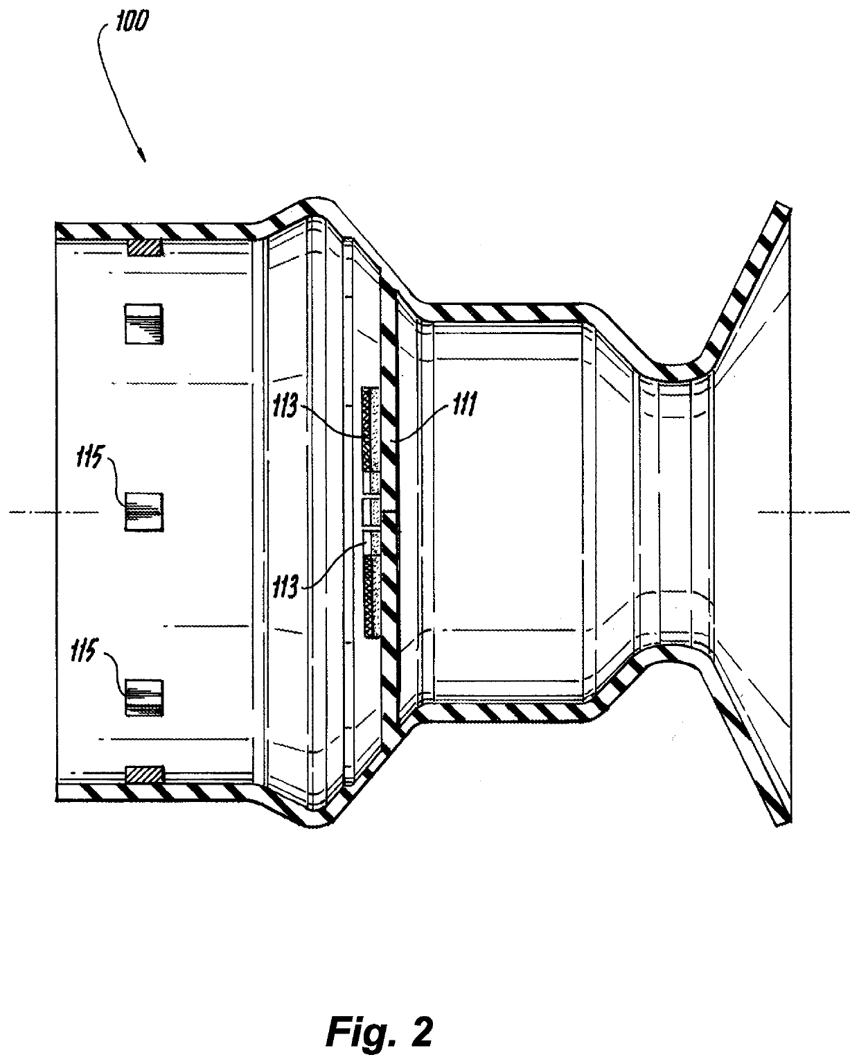
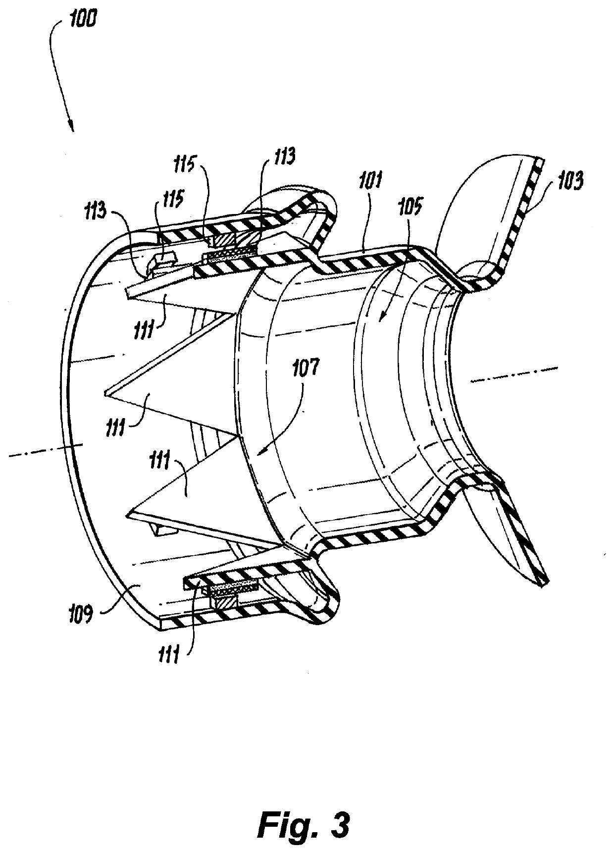
[0019]Referring to FIGS. 1-4, an eyecup 100 for an optic (e.g., a rifle scope having a display that emits light) can include an elastic body 101 (e.g., made of rubber, silicone, or any other suitable material) forming an eye receiver 103 and a viewing cavity 105. The elastic body 101 can be configured to move between a relaxed state (e.g., as shown in FIGS. 1 and 2) and a compressed state (e.g., as shown in FIGS. 3 and 4). For example, when the eyecup 100 is mounted to an optic (e.g., on a firearm), a user can press the user's face ag...


PUM


Abstract

An eyecup for an optic can include an elastic body forming an eye receiver and a viewing cavity, the elastic body configured to move between a relaxed state and a compressed state. The eyecup can include a diaphragm formed from or attached to an inner surface of the elastic body, the diaphragm including one or more flaps configured to be in a closed position when the elastic body is in the relaxed state such that the one or more flaps block sight of an optic through the viewing cavity, and to be in an open position when the elastic body is in the compressed state such that the one or more flaps allow sight of an optic through the viewing cavity. The eyecup can include one or more magnets disposed on at least one of the one or more flaps to move with the one or more flaps, and one or more sensors disposed in a fixed location and configured to sense a magnetic field or flux thereof of the one or more magnets to sense the one or more magnets when the flaps are in or near or moving toward the open position.

Description

BACKGROUND1. Field[0001]The present disclosure relates to optics, more specifically to eyecups for optics.2. Description of Related Art[0002]Elastic eyecups are typically used on optical equipment for the user comfort and reduction of ambient light noise. However, in some cases emission of the light from the device is not desirable. Mechanical shutters or electric switches can be used to power up and down digital eye displays as needed to eliminate light emission. Traditional designs may utilize hall-effect switches and a strong magnet in a “normal to face” configuration. Such arrangements require a strong and precisely selected magnet since the magnet must provide required magnetic flux density at a specific distance. The magnetic flux density changes with temperature and magnets are made within a certain tolerance, thus it is very difficult to maintain a specified switching distance that allow traditional eyecup to function.[0003]Such conventional methods and systems have generall...

Claims


Application Information

Patent Timeline
IPC IPC(8): G02B25/00G01R33/07
CPCG02B25/001G01R33/07G03B11/04G02B23/14G02B27/02F41G1/38F41G1/32G01R33/072G02B23/16
Inventor KUCZEK, ANDRZEJ ERNESTHANSELL, ERIC
Owner SENSORS UNLTD
Why Eureka
Try Eureka