Electric wire segment and stator

a technology of electric wire and stator, which is applied in the direction of windings, dynamo-electric components, and magnetic circuit shapes/forms/construction, etc., can solve the problems of hindering miniaturization and increasing the width of the coil in the radial direction, and achieves the reduction of the permittivity of the insulating film due to the vacancy, the effect of reducing the distance between the pair of neighboring electric wires and reducing the siz

Inactive Publication Date: 2020-03-12
HONDA MOTOR CO LTD
View PDF0 Cites 0 Cited by
  • Summary
  • Abstract
  • Description
  • Claims
  • Application Information

AI Technical Summary

Benefits of technology

[0026]According to the aspect of the above-mentioned (5), the end portion of the insulating film is present on the tip side of the electric wire with respect to the bent section. Here, since the portions of the pair of neighboring electric wires disposed closer to the tip side of the electric wire compared to the bent section are arranged along the first direction, since the insulating film is present closer to the tip side of the electric wire compared to the bent section, the insulating film can be disposed in the vicinity of the bent section having a small distance to the other pair of electric wires, and insulating properties between the pair of neighboring electric wires can be secured.
[0027]Accordingly, a distance between the pair of neighboring electric wires can be reduced, and the electric wire segment can be reduced in size in the arrangement direction.
[0028]According to the aspect of the above-mentioned (6), since the insulating film has a vacancy formed therein and has a permittivity lower than that of a material that forms the insulating film, a permittivity of the insulating film due to the vacancy is reduced. Accordingly, when used as the insulating film of the coil used at a high voltage, occurrence of partial discharge in the insulating film can be minimized. Accordingly, an insulating performance of the insulating film can be improved. In addition, since the vacancy is formed of a hollow capsule, since an air layer is present in the insulating film, a thermal resistance of the entire insulating film can be improved. Accordingly, it is possible to provide an insulating film having good thermal resistance and insulating properties and an electric wire segment including the same.
[0029]According to the aspect of the above-mentioned (7), it is possible to provide an excellent stator including a small electric wire segment in which a distance between a pair of neighboring electric wires can be reduced while securing insulating properties between the electric wires.

Problems solved by technology

Accordingly, a width of the coil in the radial direction is increased, which may be a cause of miniaturization being hindered.

Method used


Image

  • Electric wire segment and stator
  • Electric wire segment and stator
  • Electric wire segment and stator

Examples


first embodiment

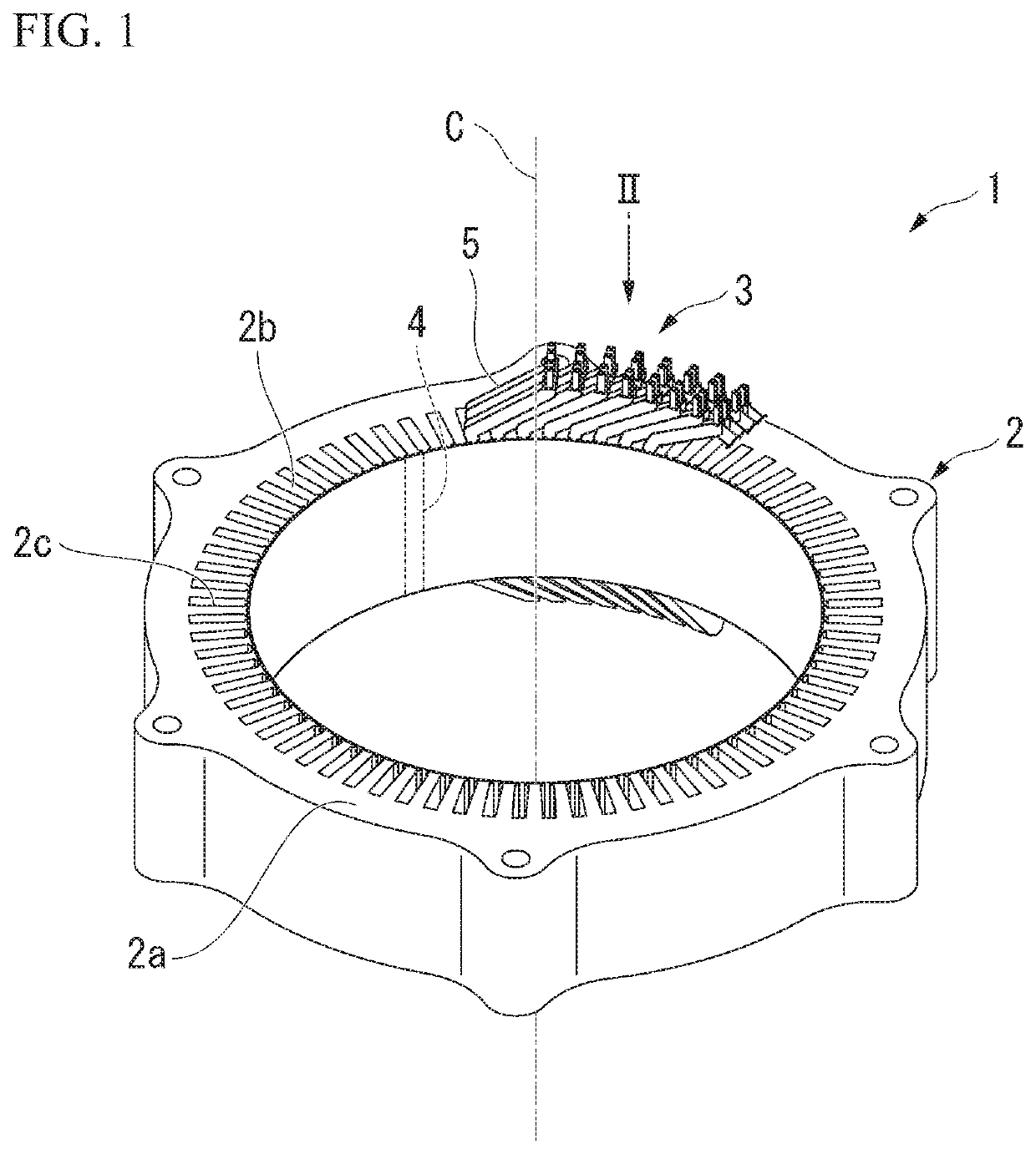
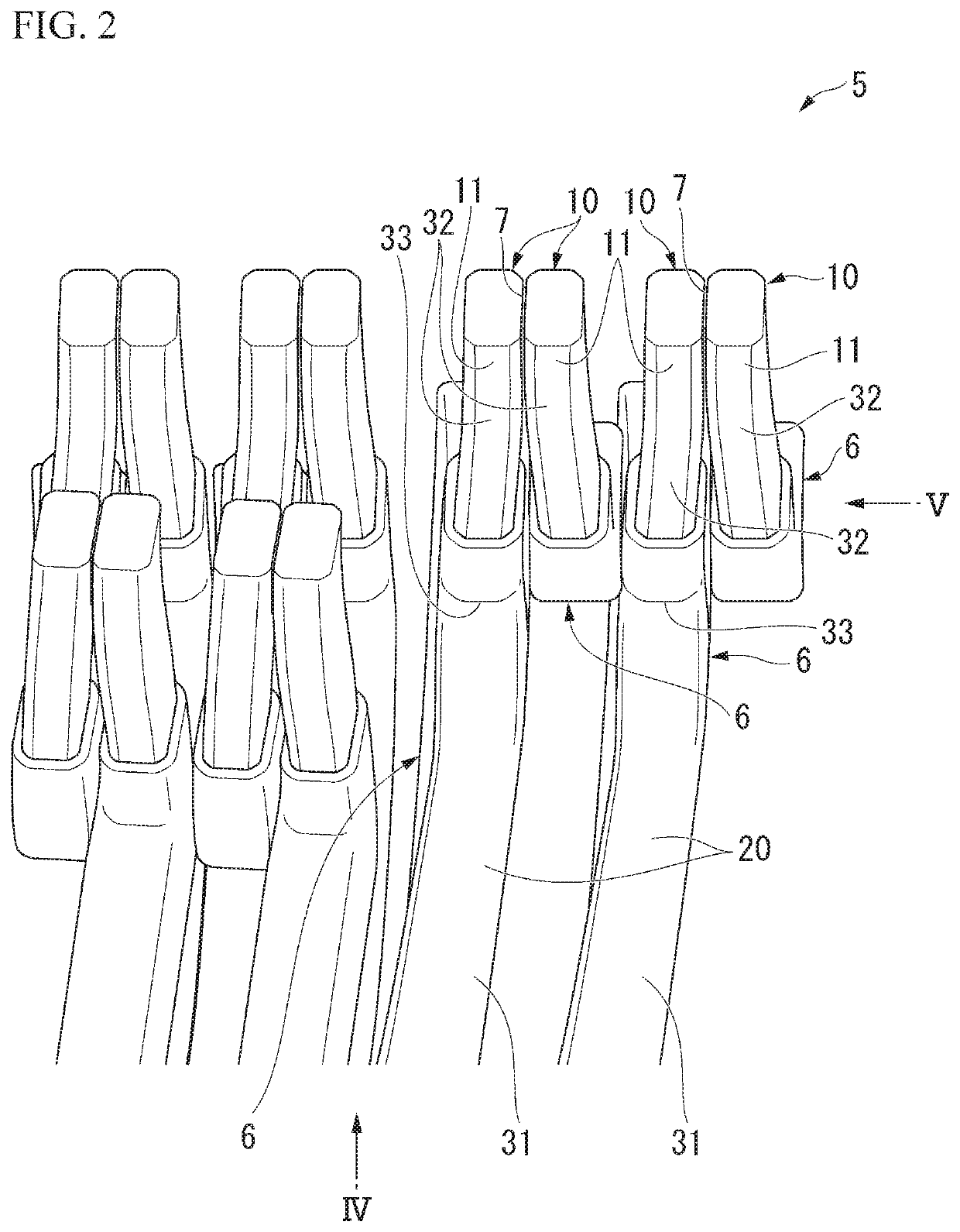
[0038]FIG. 1 is an external perspective view of a stator 1. In addition, FIG. 2 is an enlarged view of a portion II in FIG. 1.

[0039]The stator 1 includes a stator core 2 and a coil 3. Further, in FIG. 1, a part of the coil 3 will be omitted for convenience of description.

[0040]The stator core 2 is formed in an annular shape about an axis C. In the following description, a direction along the axis C may be referred to as an axial direction, a direction perpendicular to the axis C may be referred to as a radial direction, and a direction around the axis C may be referred to as a circumferential direction. The stator core 2 has a core main body 2a and teeth 2b.

[0041]The core main body 2a is formed in an annular shape. The teeth 2b protrude from the core main body 2a inward in the radial direction. The plurality of teeth 2b are formed in the circumferential direction. Slots 2c are provided between the teeth 2b. A rotor (not shown) is disposed inside inner circumferential sections of th...

second embodiment

[0071]Next, a second embodiment according to the present invention will be described. FIG. 7 is a view of an electric wire segment according to the second embodiment when seen in a circumferential direction. The embodiment is distinguished from the above-mentioned embodiment in that the insulating film 20 has a step section 28.

[0072]In the following description, components the same as those in the above-mentioned first embodiment are designated by the same reference numerals and description thereof will be appropriately omitted. In addition, reference numerals related to components other than those disclosed in FIG. 7 will appropriately refer to FIG. 1 to FIG. 6.

[0073]As shown in FIG. 7, the insulating films 20 disposed on the two side surfaces 11c and 11c of the electric wires 6 have the step sections 28. The step sections 28 connect the inner surfaces 11a and the outer surfaces 11b. The step sections 28 is formed in a recessed shape from one side toward the other side in the axial...


PUM


Abstract

An electric wire segment includes a pair of electric wires, the respective electric wires being arranged in a first direction and having an exposed conductor section in which a conductive material is exposed by having an insulating film peeled off at an end portion thereof, and the exposed conductor sections of the respective electric wires being disposed at positions corresponding to each other, and a coupling section in which the pair of electric wires are coupled to each other at the exposed conductor sections thereof, wherein a peeling amount of the insulating films on facing sides of the exposed conductor sections in which the pair of electric wires face each other is larger than a peeling amount of the insulating films on outward sides of the exposed conductor sections which is opposite to the facing sides in the first direction.

Description

CROSS-REFERENCE TO RELATED APPLICATION[0001]Priority is claimed on Japanese Patent Application No. 2018-170345, filed Sep. 12, 2018, the content of which is incorporated herein by reference.BACKGROUND OF THE INVENTIONField of the Invention[0002]The present invention relates to an electric wire segment and a stator.Description of Related Art[0003]In the related art, in a rotating electric machine, various technologies for joining tip portions of coils that are inserted into slots of a stator have been proposed.[0004]For example, Japanese Unexamined Patent Application, First Publication No. 2008-154433 discloses a method of joining a pair of exposed conductor sections (a pair of electric wires) constituted by linear sections (exposed conductor sections) of two electric wire segments in an 8-layer 4-row electric wire segment. According to the technology disclosed in Japanese Unexamined Patent Application, First Publication No. 2008-154433, the exposed conductor sections can be joined t...

Claims


Application Information

Patent Timeline
Patent Type & Authority Applications(United States)
IPC IPC(8): H02K3/52H02K1/14H02K1/16H02K3/48H02K3/32H02K15/00
CPCH02K3/522H02K1/148H02K1/16H02K3/48H02K3/325H02K15/0056H02K3/04H02K3/28H02K3/12H02K3/38H02K15/0081
Inventor AZUSAWA, KEISUKEKANEKO, RYOTARONISHIYAMA, TADAO
Owner HONDA MOTOR CO LTD
Why Eureka
Try Eureka