Imprint method, imprint apparatus, method of manufacturing article

a technology of imprinting apparatus and imprinting method, which is applied in the direction of photomechanical apparatus, nanoinformatics, instruments, etc., can solve the problems of not being able to correct a higher-order shape such as an arc or the like, limiting the number of actuators that can be arranged on the side surface of the mold, and difficult to relativly deform the shape of the mold pattern and the transfer region of the substra

Inactive Publication Date: 2020-03-19
CANON KK
View PDF1 Cites 4 Cited by
  • Summary
  • Abstract
  • Description
  • Claims
  • Application Information

AI Technical Summary

Benefits of technology

[0005]The present invention provides an imprint method advantageous in the point of accuracy of an imprint material pattern to be formed on a substrate.

Problems solved by technology

However, although the technique disclosed in Japanese Patent Laid-Open No. 2008-504141 is suitable for correcting the magnification or a low-order shape such as a rhombus or the like, it is not suitable for correcting a higher-order shape such as an arc or the like because there is a limit to the number of actuators that can be arranged on the side surface of the mold.
In particular, if the difference between the linear expansion coefficient of the mold and that of the substrate is small, it will be difficult to relatively deform the shape of the pattern of the mold and the shape of the transfer region of the substrate.

Method used


Image

  • Imprint method, imprint apparatus, method of manufacturing article
  • Imprint method, imprint apparatus, method of manufacturing article
  • Imprint method, imprint apparatus, method of manufacturing article

Examples


Embodiment Construction

[0017]Preferred embodiments of the present invention will be described below with reference to the accompanying drawings. Note that the same reference numerals denote the same members throughout the drawings, and a repetitive description thereof will not be given.

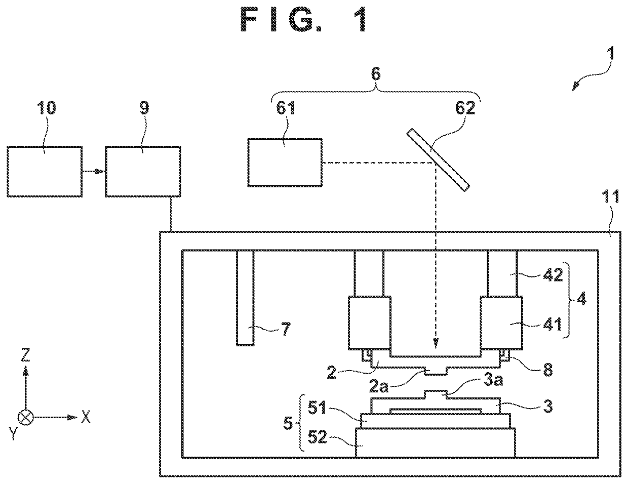
[0018]FIG. 1 is a schematic view showing the arrangement of an imprint apparatus 1 as one aspect of the present invention. The imprint apparatus 1 is a lithography apparatus that forms an imprint material pattern on a substrate by using a mold and is employed in a process of manufacturing a semiconductor device or a liquid crystal display element or a process of replicating the mold (process of manufacturing a replica mold). In this embodiment, the imprint apparatus 1 brings a mold and an imprint material supplied on a substrate into contact with each other and applies a curing energy on the imprint material to form a pattern of a cured product onto which the concave-convex pattern of a mold has been transferred.

[0019]A cur...


PUM

PropertyMeasurementUnit
wavelength rangeaaaaaaaaaa
thicknessaaaaaaaaaa
sizeaaaaaaaaaa

Abstract

The present invention provides an imprint method of forming a pattern of an imprint material on a substrate by using a mold, the method including obtaining, before bringing the mold and the imprint material into contact with each other, a correction parameter for correcting deformation of a pattern of the mold caused by bringing the mold and the imprint material on the substrate into contact with each other, and reducing the deformation of the pattern of the mold by moving at least one of the mold and the substrate by a moving unit configured to relatively move the mold and the substrate in a direction parallel to a surface of the substrate in accordance with the correction parameter in a state in which the mold and the imprint material on the substrate are in contact with each other.

Description

BACKGROUND OF THE INVENTIONField of the Invention[0001]The present invention relates to an imprint method, an imprint apparatus, and a method of manufacturing an article.Description of the Related Art[0002]An imprint technique for transferring a pattern formed on a mold onto a substrate has received attention as a lithography technique used for manufacturing a semiconductor device. In an imprint apparatus that uses the imprint technique, a mold and an imprint material on a substrate are brought into contact with each other, and the imprint material is cured in this state. Then, the mold is separated from the cured imprint material on the substrate to transfer the pattern of the mold to the substrate.[0003]The pattern of the mold needs to be transferred with high accuracy to the substrate in an imprint apparatus. Thus, a technique for correcting the shape of a pattern (pattern region) of a mold and a technique for correcting a transfer region (shot region) on a substrate are proposed...

Claims


Application Information

Patent Timeline
Patent Type & Authority Applications(United States)
IPC IPC(8): B29C43/58B29C43/02
CPCB29C43/58B82Y40/00B29C43/021G03F7/0002B82Y10/00G03F7/2002H01L21/027B29C59/02
Inventor OKADA, TETSUJIASANO, TOSIYAMURAKAMI, YOSUKE
Owner CANON KK
Why Eureka
Try Eureka