Wave power device

a power device and wave technology, applied in the direction of engine fuction, machine/engine, engine energy generation, etc., can solve the problems of large force accumulation on the effector, large system size, and high cost, and achieve the effect of high damage margin

Active Publication Date: 2020-03-19
WAVEPISTON
View PDF0 Cites 2 Cited by
  • Summary
  • Abstract
  • Description
  • Claims
  • Application Information

AI Technical Summary

Benefits of technology

[0014]The object of the invention is to present a wave power device that can extract energy from the horizontal component of water waves, where the power take-off system have a high margin against damage in high waves, because the effectors are self-centering which reduces the probability of the effectors to be forced towards positions beyond their design limit.

Problems solved by technology

However, the longer stroke length the heavier and costlier the system will be.
When using devices for extracting energy from the horizontal component of the wave movement, drift of the effectors present a technical problem.
This is a major technological problem, as an effector already offset towards one end of its maximum travel distance, can only travel a short further distance before hitting the end of the travel length.
Furthermore, when the free travel of the effector is blocked, large forces may build up on the effector due to the discontinued flow of the moving wave.
This system is, however both tedious and costly to implement, as it require that the structure, in addition to carry wave forces, also have to cope with the internal forces caused by the activated return springs.
Furthermore, the installed springs are installed in a marine environment containing high level of chloride and will be subjected to millions of load cycles, which makes them prone to fatigue failure.

Method used


Image

  • Wave power device
  • Wave power device
  • Wave power device

Examples


Embodiment Construction

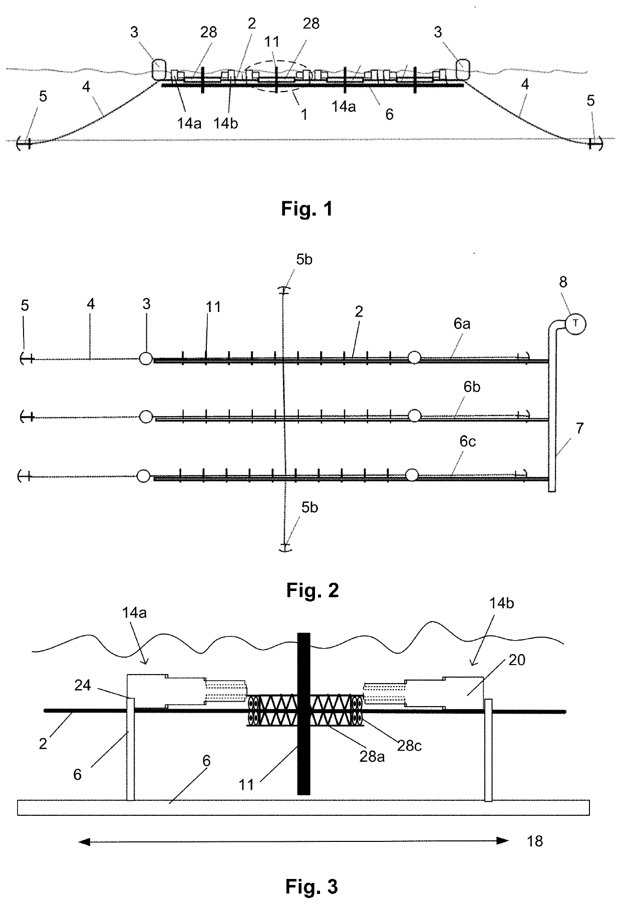
[0079]FIG. 1 shows a schematic overview of a wave power device according to an embodiment of the present invention. The substantially stationary member is held stationary in the water by two buoys 3, two mooring chains 4 and two anchors 5. The substantially stationary member 2 is mounted with four effector modules 1, each comprising an effector 11, means 28 for stabilizing and easing the movement of the effector along the length axis of the substantially stationary member 2 and two hydraulic rams 14a, 14b, symmetrically arranged around each effector.

[0080]The effector 11 is a plate-like structure, which is pushed back and forth by the oscillating action of the wave movement. Besides of forces pushing the effector back and forth, the effector will also experience non-symmetric loads due to non-uniformities in the wave movement. To handle the non-symmetric loads the effector 11 may be mounted on an effector-frame 28a, including wheels 28c that run on the substantially stationary membe...


PUM


Abstract

The present invention relates to a wave power device for extracting energy from water waves. The waver power device comprise a reference structure and effectors moving relative to the reference structure. The effectors are connected 5 to two hydraulic rams, symmetrically positioned around each effector. The hydraulic rams have an effective hydraulic area which is stepwise increased as the length of the hydraulic rams are compressed and stepwise increased as the length of the hydraulic rams are increased.

Description

FIELD OF THE INVENTION[0001]The invention relates to wave power devices for extracting energy from water surface waves, in particular in waters such as oceans, lakes or any other waters where water surface waves are generated by wind or other environmental influences.[0002]The invention also relates to a wave power system comprising a wave power device as well as a method of extracting power from water waves.BACKGROUND OF THE INVENTION[0003]For many years, there has been high focus on environment friendly methods for generating energy, in particular by extracting energy from wind and water waves. Contrary to popular belief, water movement resulting from waves is not a vertical movement, but rather a circular movement comprising a horizontal, as well as a vertical component. Thus, a submerged vertical plate and a submerged horizontal plate are subjected to forces of similar magnitude, and are thus equally suited to extract energy from waves.[0004]Most of the prior art systems and met...

Claims


Application Information

Patent Timeline
Patent Type & Authority Applications(United States)
IPC IPC(8): F03B13/22F03B13/18
CPCF03B13/1875F03B13/185F03B13/22F03B13/18F03B13/187F05B2260/406Y02E10/30
Inventor VON BÜLOW, MARTINGLEJBØL, KRISTIANMØLLER, CLAUS SCHMIDT
Owner WAVEPISTON
Why Eureka
Try Eureka