
Clamping ring and shell structure having the same

a technology of a shell structure and a clamping ring, which is applied in the direction of insulated conductors, cables, conductors, etc., can solve the problems of premature deformation and fracture, reduced service life prone to deformation and fracture of the joint, so as to reduce the damage of the clamping ring, improve the yield and service life of the finished product, and reduce the effect of fracture damag

Active Publication Date: 2020-03-19
CHICONY POWER TECH CO LTD
View PDF2 Cites 0 Cited by
  • Summary
  • Abstract
  • Description
  • Claims
  • Application Information

AI Technical Summary

Benefits of technology

The present invention is a clamping ring and a shell structure that can alleviate fracture damage of the clamping ring during assembly and increase the yield and service life of the finished product. The clamping ring is designed to accommodate and position a wire passing through the shell structure. The curved portion of the clamping ring has a hollow groove that can reduce stress and prevent fracture damage due to excessive force. The deforming groove also helps to reduce material usage and build-up of clamping stress. The technical effects of this invention include increased yield, service life, and improved reliability of the assembly process.

Problems solved by technology

The rigidity of the joint between the clamping portions at two sides and the top of the existing clamping ring is too high, and the joint is prone to deformation and fracture during the assembly process.
In this case, the clamping portions at two sides always clamp the wire in a pushed state, such that the stress of deformation is concentrated at the aforementioned joint, thus causing the service life of the clamping ring to be reduced such that deformation and fracture occur prematurely.

Method used


Image

  • Clamping ring and shell structure having the same
  • Clamping ring and shell structure having the same
  • Clamping ring and shell structure having the same

Examples


Embodiment Construction

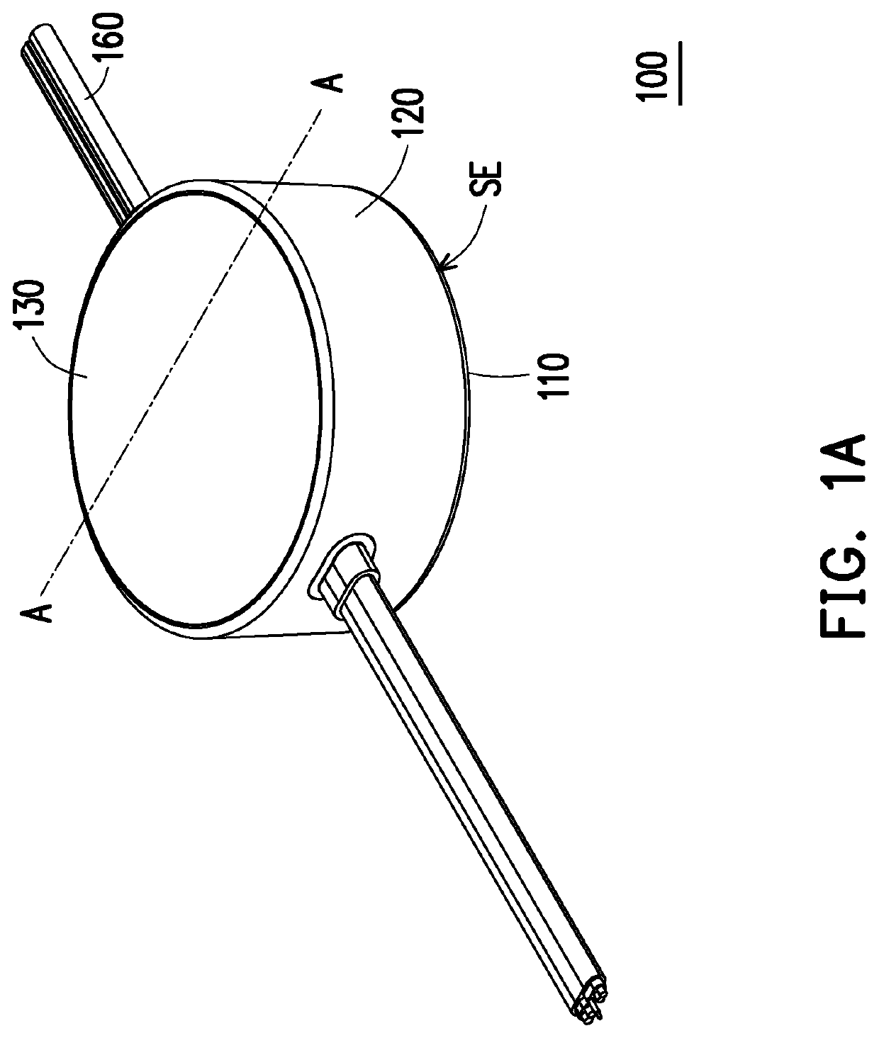
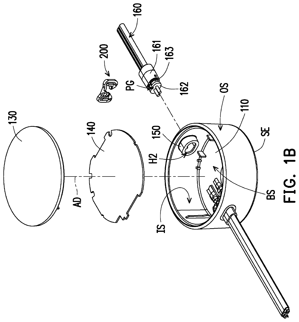
[0022]FIG. 1A is a perspective view of a shell structure according to an embodiment of the present invention. FIG. 1B is an exploded view of the shell structure of FIG. 1A.

[0023]Referring to FIG. 1A and FIG. 1B, a shell structure 100 of the present invention is adapted to carry a circuit element and is for example applied to a consumer electronic, electronic equipment, or power conversion adapter. The power conversion adapter is adapted to convert an external power source into a voltage and current value of a required specification after being transformed and rectified to be supplied to an electronic product and electronic equipment.

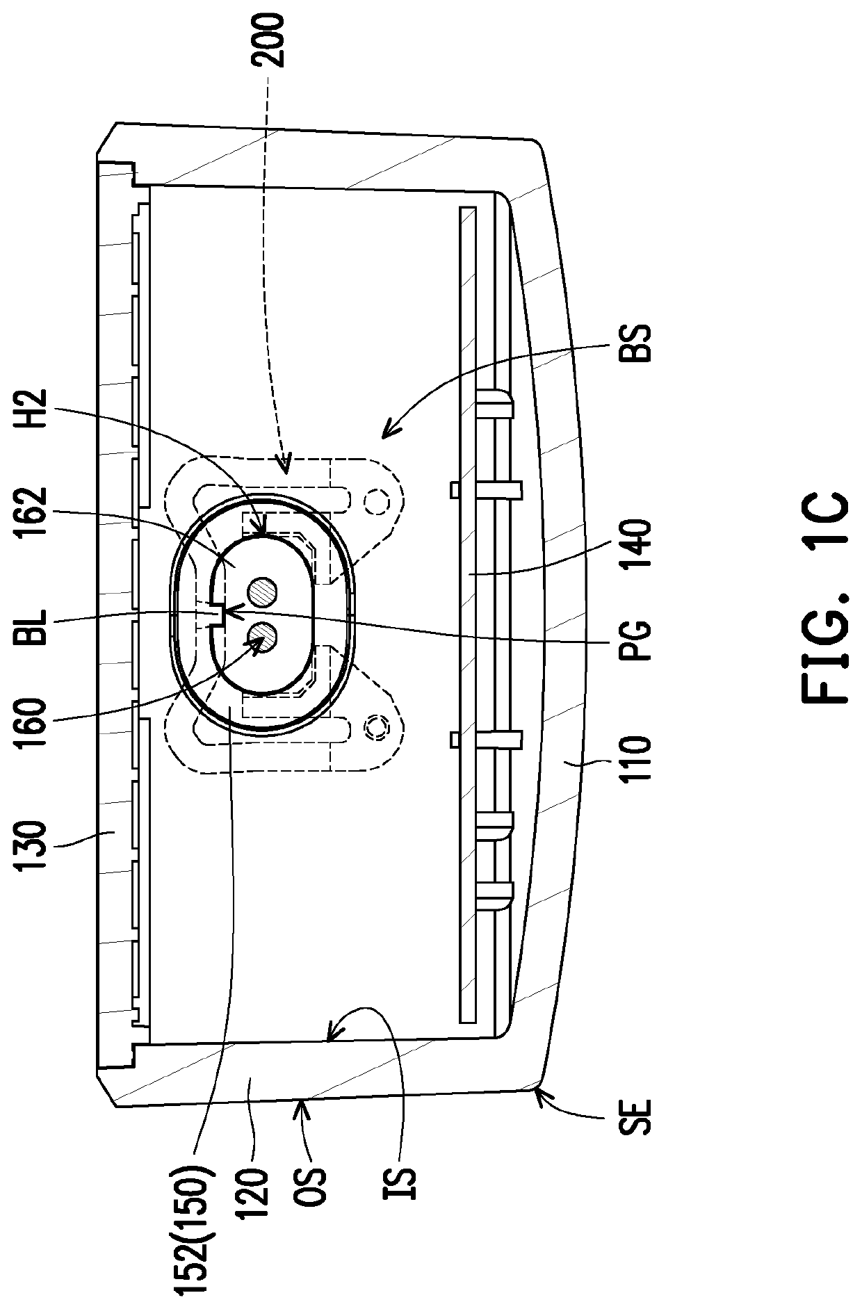
[0024]FIG. 1C is a cross section of the shell structure and clamping ring of FIG. 1A along section line A-A. FIG. 1D is an enlarged view of the wire of FIG. 1B through a shell structure. FIG. 1E is an enlarged view of a connecting portion of the shell structure of FIG. 1B.

[0025]The shell structure 100 of the present invention includes a substrate 110, a ...


PUM


Abstract

A clamping ring including a connecting beam and two engaging members is provided. The two engaging members are respectively disposed at two ends of the connecting beam, and the connecting beam and the two engaging members are adapted to accommodate and clamp a wire. At least one of the two engaging members has a curved portion, a column foot, and a hook. The curved portion has an obliquely extended neck block. The neck block is coupled to the corresponding end of the connecting beam, such that the curved portion has a vertical distance with respect to the connecting beam. A hollow groove is formed inside the curved portion. The column foot is coupled to a bottom of the curved portion opposite to the neck block, and an angle is formed between the column foot and the connecting beam. The hook is coupled to the column foot, and a deforming groove is formed between the column foot and the hook.

Description

CROSS REFERENCE TO RELATED APPLICATION[0001]This application claims the priority benefit of Taiwan application serial no. 107132486, filed on Sep. 14, 2018. The entirety of the above-mentioned patent application is hereby incorporated by reference herein and made a part of specification.BACKGROUND OF THE INVENTIONField of the Invention[0002]The present invention relates to a clamping ring and a shell structure having the same, and more particularly, to a clamping ring holding a wire to prevent it from coming loose.Description of Related Art[0003]The existing electronic connector with waterproof function undergoes a waterproof treatment mainly in the structure of two regions, one is a region of the shell connected to a gap, and the other is a joint of a wire and a wire hole of the shell.[0004]The wire is bonded to the wire hole in the following manner. The wire is correspondingly inserted into the wire hole of the shell, and an external force is applied to push the wire inward, such ...

Claims


Application Information

Patent Timeline
Patent Type & Authority Applications(United States)
IPC IPC(8): F16L3/13H02G3/08F16L3/12
CPCF16L3/1222H01B7/0045F16B2/241H02G3/045H02G3/088F16L3/13H02G3/0625H02G3/083F16B2/243F16B21/186H02G3/0691
Inventor CHENG, CHAO-CHENG
Owner CHICONY POWER TECH CO LTD
Learn More