Display assemblies disposed inside mechanical keys in a mechanical keyboard

a technology of mechanical keys and display assemblies, which is applied in the field of mechanical keyboards, can solve the problems of compromising its applicability, affecting the use of mechanical keys, and limited operation life, and achieves the effects of less prone to wear and damage, easy assembly and manufacturing, and long operation li

Active Publication Date: 2020-03-19
ELGATO IDISPLAY LTD
View PDF1 Cites 0 Cited by
  • Summary
  • Abstract
  • Description
  • Claims
  • Application Information

AI Technical Summary

Benefits of technology

[0004]A major objective of the present invention is to provide a mechanical keyboard where display modules are configured on the keycaps so that they will move along with the keycaps and they are as such visible to a user from different angles. The display modules may be installed in ordinary mechanical keys, achieving simpler manufacturing. Signal transmission elements run through the various components and connect to a bottom side of a circuit board. The signal transmission elements therefore are less prone to wear and damage, enhancing their operation lives.
[0006]Through the above structure, a depressed keycap engages the base and signal is transmitted to the circuit board. Each display module is fixed in a keycap through the engagement between a frame and a base. As each keycap is joined to the keyswitch through the base, the display module moves up and down along with the keycap. Then, regardless whether a keycap is depressed or not, each display module is besides the transparent piece at all times, and a user may always see the content on the display module. The display module may show various content provided by the circuit board. The signal transmission element runs around the base and the circuit board, and connects to a bottom side of the circuit board. When the keycap is depressed and the display module moves as well, the signal transmission element is bent and pressure is evenly distributed across the entire signal transmission element. The signal transmission element is as such less prone to wear and damage, and has a longer operation life. As each display assembly is directly housed in an ordinary mechanical key without designing a new mechanical key for the display assembly, the mechanical keyboard is easier to assembly and manufacture. The present invention as such resolves the problem of conventional mechanical keys that display screens are limited to certain viewing angle, operation life is shorter, and a new design is required.

Problems solved by technology

When the keycap is not depressed, the LED display is visible only at certain angle, compromising its applicability.
The operation life is also limited, causing a higher usage cost.
In addition, such a mechanical key requires a different modular design and is difficult to integrate with existing mechanical key.
The design, manufacturing, and assembly are all more complex and inconvenient.
This design also requires a different modular design and is difficult to integrate with existing mechanical key.

Method used


Image

  • Display assemblies disposed inside mechanical keys in a mechanical keyboard
  • Display assemblies disposed inside mechanical keys in a mechanical keyboard
  • Display assemblies disposed inside mechanical keys in a mechanical keyboard

Examples


first embodiment

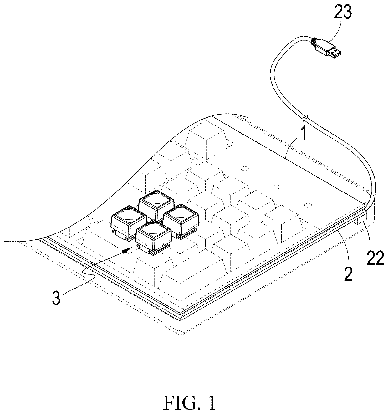
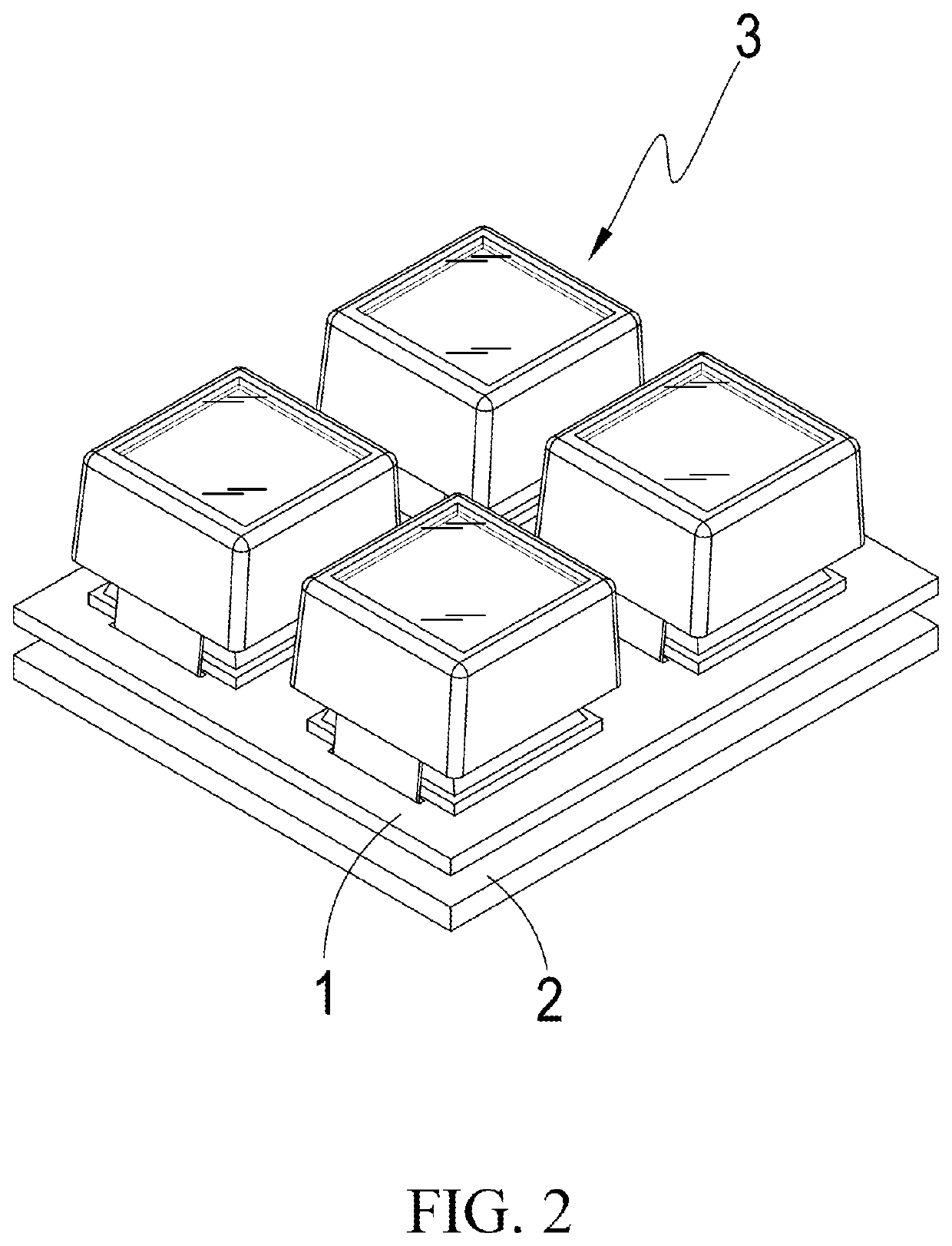
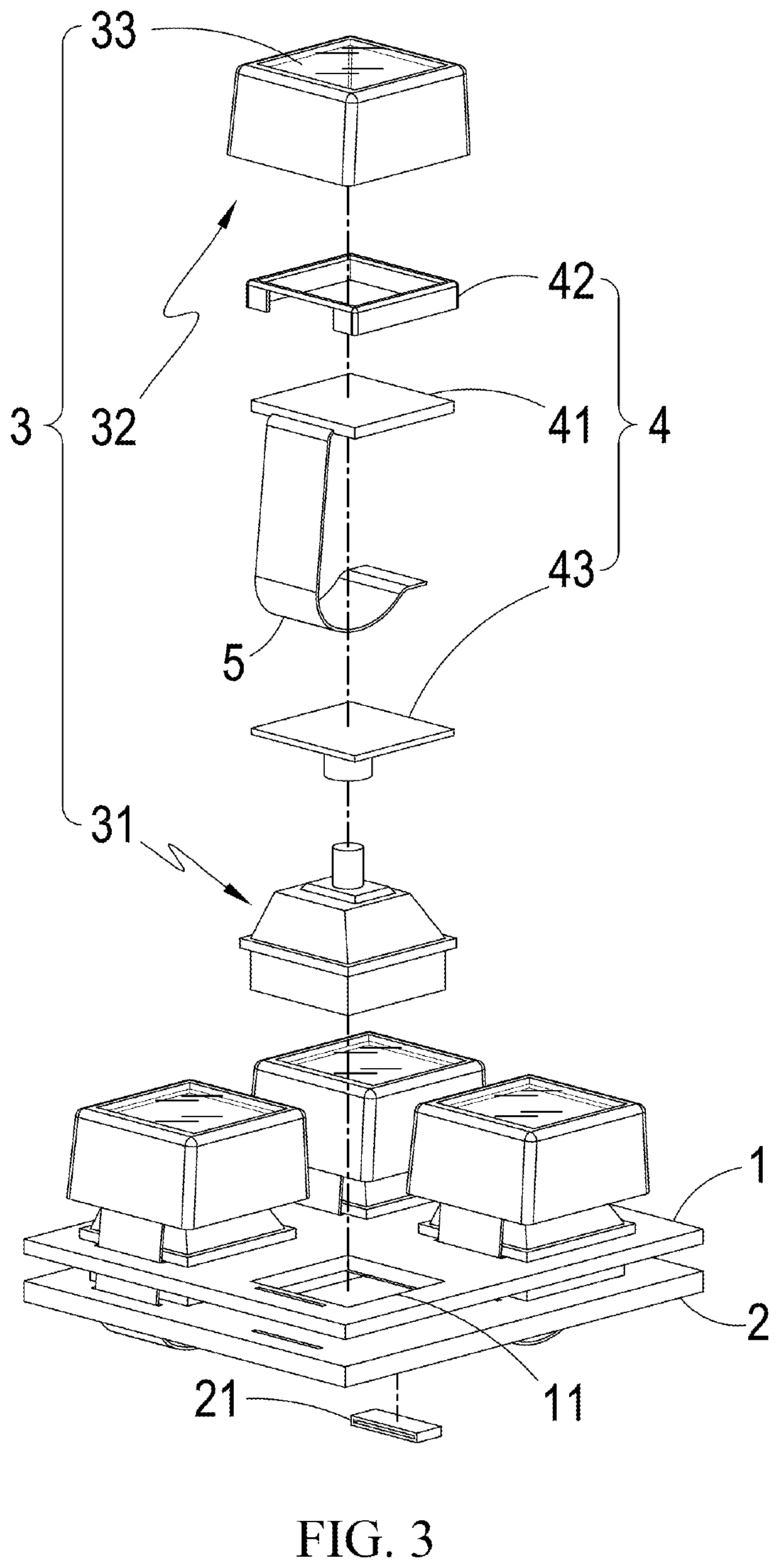
[0023]As shown in FIGS. 1 to 3, a mechanical keyboard according to the present includes a base plate 1, a circuit board 2, multiple mechanical keys 3, multiple display assemblies 4, and multiple signal transmission elements 5. The base plate 1 has multiple through openings 11. The circuit board 2 is disposed to a side of the base plate 1. Each mechanical key 3 is disposed at an opening 11 and connected to the circuit board 2 through the opening 11. Each display assembly 4 is disposed inside a mechanical key 3. Each signal transmission element 5 connects a display assembly 4 to the circuit board 2.

[0024]Each mechanical key 3 includes a keyswitch 31, a keycap 32, and at least a transparent piece 33. The keyswitch 31 is an ordinary mechanical switch connected to the circuit board 2 through an opening 11. The keycap 32 is mounted on the keyswitch 31 through a display assembly 4. The transparent piece 33 is configured to a top side of the keycap 32. It is also possible that the entire ke...

second embodiment

[0030]As shown in FIGS. 8 to 10, the present invention is similar to the previous embodiment except that each frame 42a has a number of notches 421a along bottom edges and a number of slots 422a on circumferential walls of the frame 42a. Each keycap 32a has protrusion 321a on inner walls, each corresponding to a notch 421a. On the other hand, each base 43a has a number of blocks 431a along its circumference, each corresponding to a slot 422a. Through the engagement between the notches 421a and the protrusions 321a, each frame 42a is more reliably positioned in a keycap 32a. Similarly, through the engagement between the slots 422a and the blocks 431a, each base 43a, and therefore each display module 41a, is more reliably coupled to a frame 42a.

third embodiment

[0031]FIG. 11 shows the present invention. As illustrated, the present embodiment is similar to the previous embodiments except that each keycap is the transparent piece 33b itself In other words, the transparent pieces 33b may have various embodiments as long as it may allow a user to view the display modules 41b clearly and conveniently.


PUM


Abstract

The mechanical keyboard includes a base plate having multiple through openings, a circuit board disposed to a side of the base plate, multiple mechanical keys disposed at the through openings and connected to the circuit board. Each mechanical key includes a keyswitch, a keycap, and at least a transparent piece. The keyswitch is connected to the circuit board. The keycap is mounted on the keyswitch, and the transparent piece is configured to a top side of the keycap. There are multiple display assemblies, each disposed inside a mechanical key between the keycap and the keyswitch. Each display assembly is data-linked to the circuit board through a signal transmission element. The display assemblies may be installed on conventional mechanical keys and may be viewed from different angles. The mechanical keyboard also has longer operation life.

Description

BACKGROUND OF THE INVENTION(a) Technical Field of the Invention[0001]The present invention is generally related to mechanical keyboards, and more particular to a mechanical keyboard where each key has a display module.(b) Description of the Prior Art[0002]R.O.C. Taiwan Patent No. M400080 discloses a teaching that a LED display is placed between the keycap and circuit board and the LED display is fixed to the circuit board. The LED display therefore does not move with the keycap. When the keycap is not depressed, the LED display is visible only at certain angle, compromising its applicability. The operation life is also limited, causing a higher usage cost. In addition, such a mechanical key requires a different modular design and is difficult to integrate with existing mechanical key. The design, manufacturing, and assembly are all more complex and inconvenient.[0003]As such, there are teachings that the LED display is configured with the keycap so that it will move up and down with...

Claims


Application Information

Patent Timeline
Patent Type & Authority Applications(United States)
IPC IPC(8): G06F3/023H01H13/83
CPCG06F3/0238H01H13/83G06F3/0202H01H2215/05H01H2219/016H01H2219/048H01H2221/07G06F3/0412G06F2203/04809H01H13/705
Inventor SUN, JEN-WEN
Owner ELGATO IDISPLAY LTD
Why Eureka
Try Eureka