Eureka AIR delivers breakthrough ideas for toughest innovation challenges, trusted by R&D personnel around the world.

High-torque ratchet wrench

a ratchet wrench and high-torque technology, applied in the field of ratchet wrenches, can solve the problems of certain friction force and the inability to completely smooth the surface of parts and elements, and achieve the effect of simple and compact structure, enhanced torque transfer capability, and new and unique torque transfer structur

Active Publication Date: 2020-03-26
HUAZHONG HE
View PDF0 Cites 0 Cited by
  • Summary
  • Abstract
  • Description
  • Claims
  • Application Information

AI Technical Summary

Benefits of technology

The present invention is a unique wrench design that allows for better torque transfer and is simple and compact in structure. It uses a resilient reset member to transfer rotation from the handle to the pin, creating a stable structure under pressure between the pin and the drive member. This force of friction rotates the drive member, allowing for efficient torque transfer between the handle and the drive member. This new design enhances the functionality of the wrench while keeping it simple and compact.

Problems solved by technology

In addition, the surface of parts and elements cannot be completely smooth, so a certain force of friction exists between the second drive face and the relief due to mutual contact.

Method used


Image

  • High-torque ratchet wrench
  • High-torque ratchet wrench
  • High-torque ratchet wrench

Examples


embodiment 1

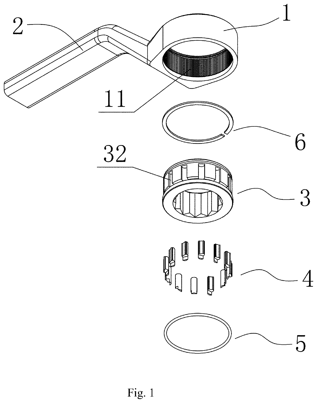
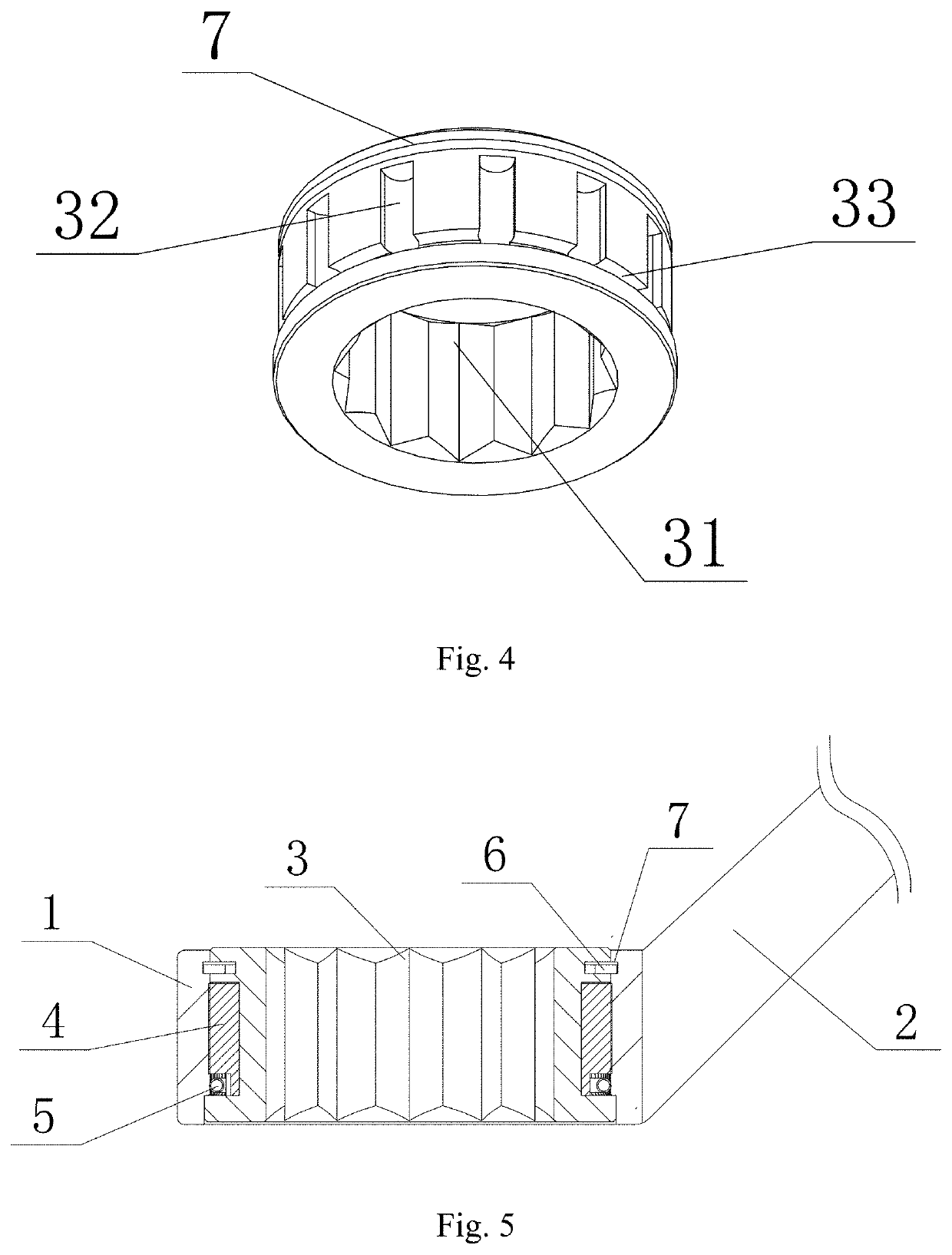
[0040]As illustrated in FIG. 1, the wrench in this embodiment comprises a wrench body having a driving aperture 1 and a handle 2, wherein the driving aperture 1 has the structure of a rounded through hole and has only one end disposed on the handle 2, a drive member 3 is arranged in the driving aperture 1 and an axial position-limiting mechanism is used to prevent the drive member 3 from axially moving from the driving aperture 1 and further being released from the driving aperture 1, and the axial position-limiting mechanism in this embodiment is realized by adopting the structure of a snap spring 6 mounted in a snap spring recess 7 as shown in FIGS. 4-5; As illustrated in FIG. 4, a through hole 31 having a quincuncial section is arranged in the center of a drive member 3 to fit a fastener, such as bolts, so as to transfer the rotational torque from the handle 2 to the fastener.

[0041]As illustrated in FIGS. 1, 4, 5 and 6, the external side wall of the drive member 3 and the inner h...

embodiment 2

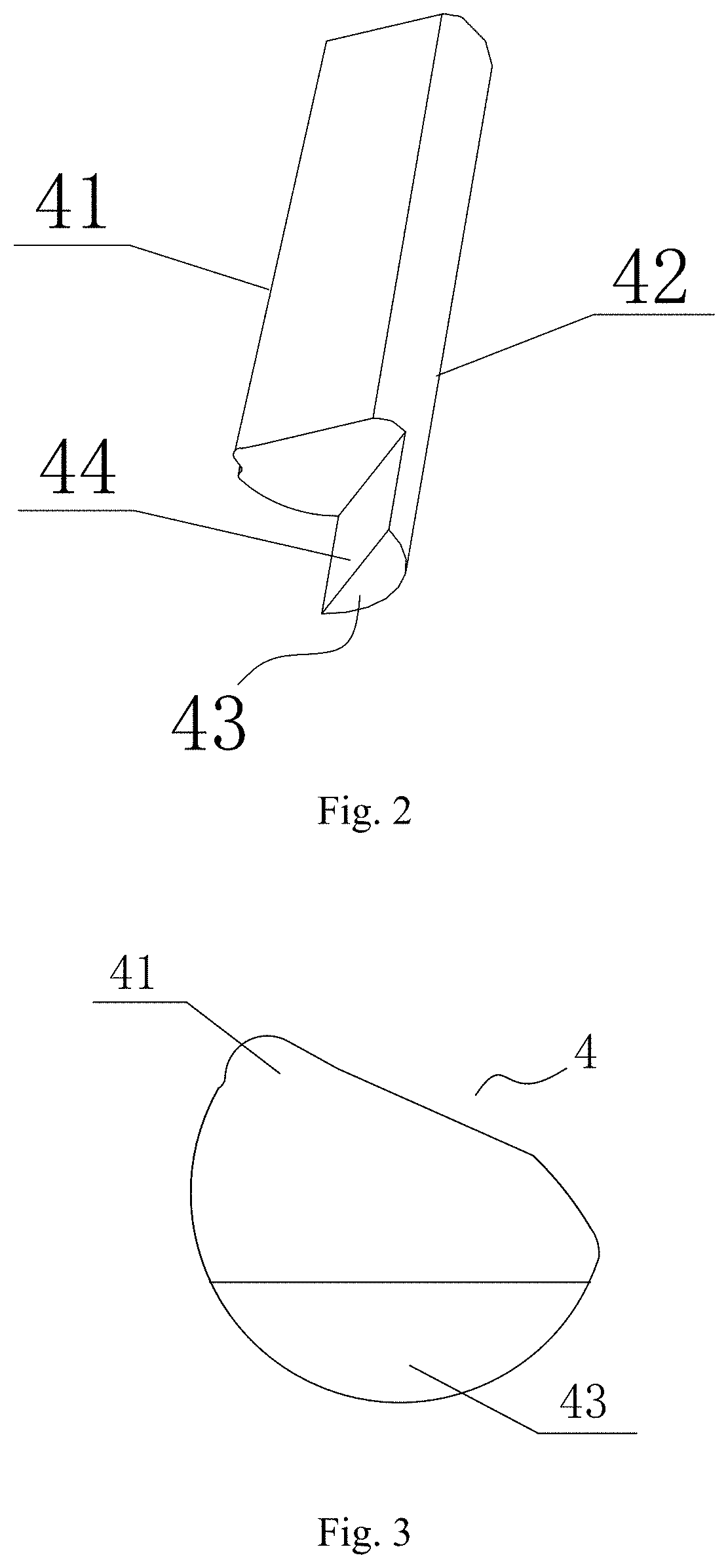
[0056]As illustrated in FIGS. 9, 10, 11, 12 and 13, the difference from Embodiment 1 is that the ratchet teeth 12 are evenly arranged on the inner hole wall 11 of the driving aperture 1 in this embodiment, the extension direction of the ratchet teeth 12 is parallel to the central axis of the driving aperture 1 and both sides of the convex part are in the shape of tool edge so that convex part 41 can form a ratchet structure matching the ratchet teeth 12.

[0057]The principle of engagement of the ratchet teeth 12 with the relief 41 (i.e. snap teeth, the same below) is similar to that in Embodiment 1, as shown below:

[0058]As illustrated in FIG. 12, the spring ring 5 contracts under the spring force, the spring ring 5 applies to the bearing face 44 of the pin 4 the elastic force which tends towards the center of the spring ring 5 (i.e. the central axis of the driving aperture 1) pushes the pin 4 to rotate clockwise (as shown in the dotted arrow in FIG. 7) so as to make the relief 41 of t...

embodiment 3

[0063]As illustrated in FIGS. 14, 15 and 16, the difference from Embodiment 2 is that the inner hole wall 11 of the driving aperture 1 is used as the first drive face having the pin recess 32 and the external side face of the drive member 3 is used as the second drive face having the ratchet teeth 12 in this embodiment, and for other structures and operating principles of this embodiment, refer to Embodiment 2, so they will not be repeated herein.

[0064]It is understood that the spring ring 5 in Embodiments 1, 2 and 3 described above can also be arranged in a circle surrounded by all pins 4, and the spring ring 5 is pressed against the bearing face 44 of the spring pressing portion 43 of all pins 4 at the same time, and the elastic force that is produced by outward expansion of the spring ring 5 is employed to reset the pins 4.

[0065]In addition, FIGS. 17 and 18 illustrate the wrenches having two different structures, wherein:

[0066]in the wrench as shown in FIG. 17, both ends of the h...


PUM


Abstract

The present invention discloses a high-torque ratchet wrench. This high-torque ratchet wrench comprises a wrench body having a driving aperture and a handle, and a drive member is disposed in the driving aperture and an axial position-limiting mechanism is disposed between the driving aperture and the drive member to limit the relative axial displacement. The external side wall of the drive member and the internal aperture side of the driving aperture form two cylindrical drive faces nested, wherein a first drive face is provided with a pin recess, a pin is rotatably mounted in the pin recess, a relief is disposed on the side face of pin, the pin is connected with a resilient reset member, the pin is rotated with the resilience of a resilient reset member, a relief is driven to stand out of the pin recess and contacts a second drive face, and the distance between the outermost end point of the relief and the central axis of the pin is greater than the minimum distance between the second drive face and the central axis of the pin. The ratchet wrench designs a unique structure used to transfer torque, greatly enhance the capability of torque transfer and simultaneously provide the whole wrench with a simple and compact structure, so that it is easy to use.

Description

FIELD OF THE INVENTION[0001]The present invention relates to a tool for tightening and disassembly, and more particularly to a ratchet wrench.BACKGROUND OF THE INVENTION[0002]A ratchet wrench is a hand tool for tightening and loosening bolts. This wrench can tighten and loosen screws or nuts by swinging at a certain angle. Two stay bars are disposed in the wrench head on the left and right sides. One or more stay teeth are arranged on the stay bars, and when screws or nuts are tightened, the teeth will be firmly pressed against the ratchet teeth. When a handle is turned in an opposite direction, stay bars will be released from the sloping surface of ratchet teeth, so that screws or nuts will not be reversed with it. If screws or nuts are to be loosened, only the reversing part is need to be switched to another stay bar.[0003]However, when a high torque is applied for turning the ratchet wrench, there will be excess stress on ratchet teeth if only a limited number of stay teeth are p...

Claims


Application Information

Patent Timeline
Patent Type & Authority Applications(United States)
IPC IPC(8): B25B13/46
CPCB25B13/463B25B13/465B25B13/04
Inventor HE, HUAZHONG
Owner HUAZHONG HE
Why Eureka
Eureka Blog
Learn More