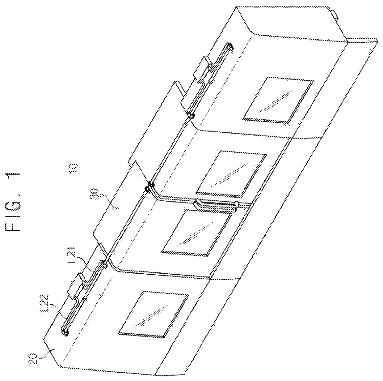
Pneumatic pressure control device and pneumatic pressure control method for automatic door

a technology of pneumatic control device and pneumatic control method, which is applied in the direction of wing accessories, servomotors, manufacturing tools, etc., can solve problems such as deteriorating controllability, and achieve the effect of reducing the exhaust speed of compressed air and preventing sudden acceleration of the door

Active Publication Date: 2020-03-26
DN SOLUTIONS CO LTD
View PDF4 Cites 2 Cited by
  • Summary
  • Abstract
  • Description
  • Claims
  • Application Information

AI Technical Summary

Benefits of technology

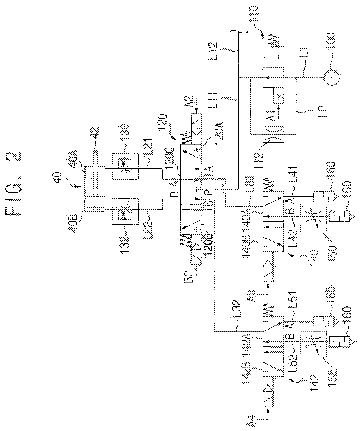
[0020]According to example embodiments, a pneumatic control device of auto door, includes a first directional control valve configured to control a direction of a compressed air supplied to a door cylinder for opening and closing a door, and second directional control valves installed in first and second exhaust lines respectively connected to first and second outlet ports of the first directional control valve.
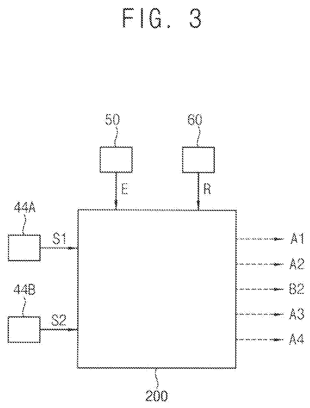
[0021]The compressed air may be exhausted from the first and second outlet ports through the second directional control valves according to an emergency stop signal, and in case that the door is not completely open or closed when an operation signal is generated after the emergency stop signal, the second directional control valve is switched to reduce an exhaust speed of the compressed air.
[0022]Accordingly, when a system is restarted after the emergency stop, sudden acceleration of the door may be prevented.
[0023]However, the effect of the invention may not be limited thereto, and may be expanded without being deviated from the concept and the scope of the present invention.

Problems solved by technology

However, when a normal operation restarts right after an emergency stop, sudden acceleration of the door may be generated thereby deteriorating controllability.

Method used


Image

  • Pneumatic pressure control device and pneumatic pressure control method for automatic door
  • Pneumatic pressure control device and pneumatic pressure control method for automatic door
  • Pneumatic pressure control device and pneumatic pressure control method for automatic door

Examples


Embodiment Construction

[0037]Hereinafter, preferable embodiments of the present invention will be explained in detail with reference to the accompanying drawings.

[0038]In the drawings, the sizes and relative sizes of components or elements may be exaggerated for clarity.

[0039]It will be understood that, although the terms first, second, third, etc. may be used herein to describe various elements, components, regions, layers and / or sections, these elements, components, regions, layers and / or sections should not be limited by these terms. These terms are only used to distinguish one element, component, region, layer or section from another element, component, region, layer or section. Thus, a first element, component, region, layer or section discussed below could be termed a second element, component, region, layer or section without departing from the teachings of example embodiments.

[0040]The terminology used herein is for the purpose of describing particular example embodiments only and is not intended ...


PUM


Abstract

A pneumatic control device of auto door includes a first directional control valve configured to control a direction of a compressed air supplied to a door cylinder for opening and closing a door, a door detection sensor configured to detect an open/close state of the door, first and second exhaust lines respectively connected to first and second outlet ports of the first directional control valve, and second directional control valves installed in the first and second exhaust lines respectively to operably exhaust the compressed air exhausted from the first and second outlet ports according to an emergency stop signal, and capable of changing positions to reduce an exhaust speed of the compressed air in case that the door is not completely open or closed when an operation signal is generated after the emergency stop signal.

Description

TECHNICAL FIELD[0001]The present invention relates to a pneumatic control device and a pneumatic control method of auto door. More particularly, the present invention relates to a pneumatic control device to automatically a door of a machine tool and a pneumatic control method using the same.BACKGROUND ART[0002]Generally, workpieces and tools may be carried into or taken out of a machine tool through a door. In a pneumatic circuit diagram of auto door for automatically opening and closing the door, an amount of a compressed air supplied to a door cylinder for opening and closing the door from a pneumatic source may be adjusted. However, when a normal operation restarts right after an emergency stop, sudden acceleration of the door may be generated thereby deteriorating controllability.DISCLOSURE OF THE INVENTIONProblems to be Solved[0003]An object of the present invention provides a pneumatic control device of auto door capable of preventing sudden acceleration after an emergency st...

Claims


Application Information

Patent Timeline
Patent Type & Authority Applications(United States)
IPC IPC(8): E05F15/72E05F15/56
CPCE05Y2800/252E05Y2900/132E05Y2400/36E05F5/10E05Y2900/608E05Y2201/41B23Q11/0825E05F15/56E05Y2201/422E05F15/72B23Q11/08E05Y2201/21E05Y2201/458E05Y2400/324E05Y2400/354E05Y2400/53E05Y2800/422F15B11/06F15B20/00F15B2211/8855F15B2211/40515F15B2211/41554F15B2211/426F15B2211/455F15B2211/46F15B2211/41509F15B2211/8606F15B2211/8616F15B2211/75F15B11/042F15B11/044F15B2211/40576F15B2211/40592F15B2211/40507F15B2211/7053F15B2211/6654F15B2211/6336F15B2211/8755
Inventor CHO, YOUNG-JEON
Owner DN SOLUTIONS CO LTD
Why Eureka
Try Eureka