Latent heat accumulator system comprising a latent heat accumulator and method for operating a latent heat accumulator system

a technology of latent heat accumulator and latent heat, which is applied in the direction of indirect heat exchangers, heating types, lighting and heating apparatus, etc., can solve the problems of damage or even destruction of heat exchanger pipes, uncontrollable ice storage devices, etc., and achieve the effect of providing heat and cold quickly and efficiently and short response tim

Inactive Publication Date: 2020-03-26
VIESSMANN GRP GMBH & CO KG
View PDF0 Cites 1 Cited by
  • Summary
  • Abstract
  • Description
  • Claims
  • Application Information

AI Technical Summary

Benefits of technology

[0028]According to an advantageous method step, in partial-load operation, a coupling strength between extraction heat exchanger and regeneration arrangement can be changed depending on a set point temperature of the heat carrier media and or a set point power of heat source or heat sink. The latent heat storage system can advantageously provide heat and cold quickly and efficiently.
[0029]According to an advantageous method step, in full-load operation, flow through the extraction heat exchanger and the regeneration arrangement can be at a maximum. Advantageously, a coupling device, for example, a mixing element, can be opened maximally in such an operating mode with short response time.

Problems solved by technology

The hydraulic circuits for the extraction and for the regeneration have to be strictly separated in order to avoid an uncontrolled thawing or freezing, which makes the ice storage device uncontrollable and in the most disadvantageous case can damage or even destroy the heat exchanger pipes due to the chipping off of ice.

Method used


Image

  • Latent heat accumulator system comprising a latent heat accumulator and method for operating a latent heat accumulator system
  • Latent heat accumulator system comprising a latent heat accumulator and method for operating a latent heat accumulator system
  • Latent heat accumulator system comprising a latent heat accumulator and method for operating a latent heat accumulator system

Examples


Embodiment Construction

[0036]In the figures, identical or equivalent components are numbered with identical reference numerals. The figures merely show examples and are understood to be non-limiting.

[0037]Direction terminology used below with terms such as “left,”“right,”“top,”“bottom,”“in front of,”“behind,”“after,” and the like are only used to improve the understanding of the figures and are never intended to represent a limitation of the generality. The represented components and elements, their design and use can vary depending on the considerations of a person skilled in the an and can be adapted to the respective applications.

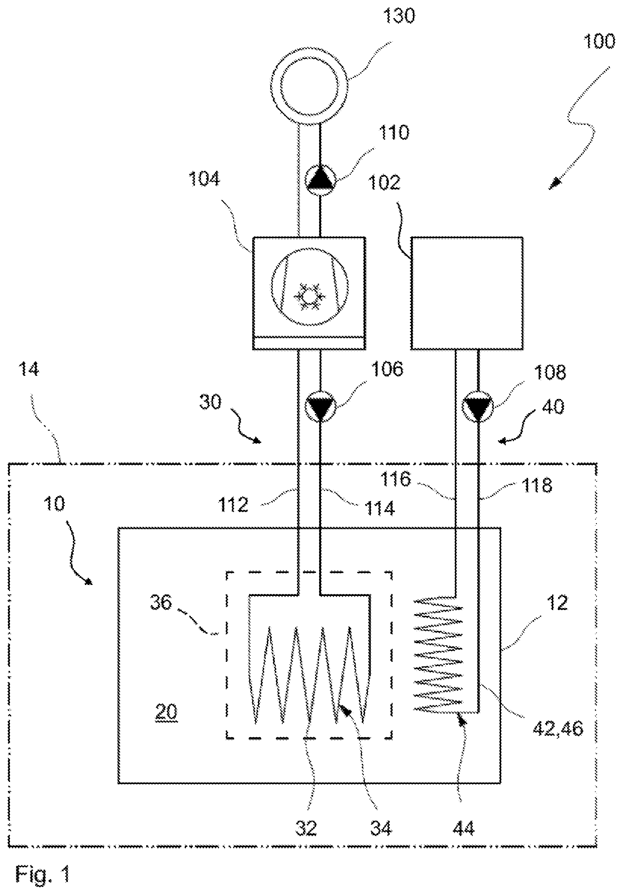
[0038]FIG. 1 represents a latent heat storage system 100 during normal operation. The latent heat storage system 100 comprises a latent heat storage device 10 which contains a storage medium 20 with latent heat, for example, water. Furthermore, the latent heat storage system 100 comprises an extraction circuit 30 which, during normal operation, in accordance with the intended ...


PUM


Abstract

A latent heat storage system includes at least one latent heat storage device which contains a storage medium with latent heat, at least one extraction circuit by means of which, in accordance with the intended purpose, heat can be extracted from the storage medium, and at least one regeneration circuit by means of which, in accordance with the intended purpose, heat can be supplied into the storage medium. The at least one latent heat storage device includes at least one extraction heat exchanger which is in contact with the storage medium and can be connected to the extraction circuit, and at least one regeneration arrangement within the storage medium, which can be connected to the regeneration circuit. A coupling device is provided, by which the at least one extraction heat exchanger can be at least temporarily coupled to the at least one regeneration arrangement for common heat extraction from the storage medium or for common heat supply into the storage medium. A corresponding operating method is also provided.

Description

BACKGROUND AND SUMMARY[0001]The invention relates to a latent heat storage system having a latent heat storage device and to a method for operating a latent heat storage system.[0002]From EP 2614330 A1, an ice storage system is known, in which an extraction heat exchanger extracts heat from an ice storage device during the healing period, until the ice storage device is thermally unloaded. During the thermal unloading, a predetermined volume around die extraction heat exchanger has completely solidified into ice. This occurs in a controlled manner. The water around the heat exchange pipes of the extraction heat exchanger solidifies in a targeted manner from the inside to the outside. In order to reload the ice storage device, after the heating period, heat is introduced into the ice storage device via a regeneration heat exchanger. In the process, the ice around the extraction heat exchanger likewise thaws again in a targeted and directed manner. The hydraulic circuits for the extra...

Claims


Application Information

Patent Timeline
Patent Type & Authority Applications(United States)
IPC IPC(8): F28D20/02
CPCF24D2220/10F28D20/023F01P2011/205F28D2020/0078F28D20/028F28D20/021F28D20/025F24F5/0017Y02E60/14
Inventor FUCHS, SVENPFANNKUCH, MORITZORTLIEB, TOBIAS
Owner VIESSMANN GRP GMBH & CO KG
Why Eureka
Try Eureka