A panel and a heating system

a heating system and panel technology, applied in the field of panels, can solve the problems of short circuit, loss of heating function, and possible problems of course very unfortunate, and achieve the effects of ensuring the safety and reliability of the panel power supply, facilitating the mechanical coupling of the panel together, and stable electrical coupling

Active Publication Date: 2020-04-02
HEAT CLICK CO AB
View PDF0 Cites 1 Cited by
  • Summary
  • Abstract
  • Description
  • Claims
  • Application Information

AI Technical Summary

Benefits of technology

[0046]The panel according to the present invention is cuttable in the sense of being possible to cut off and still be used for laying floors. This is due to the fact that the locations of the first and second longitudinal grooves are well defined, which also results in a well-defined placement of the first and second electrical end connectors and / or the first and second electrical power supply end connectors placed in the first and second grooves. Hereby, a cut off panel may be laid against another cut off panel, or may be laid against a whole panel, and would still be provided with a reliable supply of electrical energy for generating the heat in the panel, since the first and second electrical end connectors and / or the first and second electrical power supply end connectors of the panels will fit / match / meet such that a connection is made.
[0047]The electrical end connectors and / or the electrical power supply end connectors of the panel according to the present invention are at least partly separated from the mechanical panel joint coupling, i.e. from the joint coupling mechanically holding panels together. Hereby, the electrical end connectors and / or the electrical power supply end connectors are also protected from the many movements of the parts of the mechanical panel joint, and from the component wear these movement could result in.
[0048]By usage of the present invention, a secure and reliable power supply to the panel is assured. Also, the design of the electrical end connectors according to the present invention simplifies mechanical coupling of panels together, at the same time as a stable electrical coupling is provided.
[0049]Also, the end connectors of the panel according to the present invention provides for a reliable and secure electrical contact to corresponding end connectors of adjacent panels. Hereby, electrical energy to be used for creating the heat in the heat providing layer reliably reaches each one of coupled panels, and therefor also reaches the heat providing layers of each one of the panels.
[0050]The panel according to the present invention may be produced and installed cost efficiently. Since the heat may be created by use of low voltages, such as 4-60 Volts, e.g. approximately 25 Volts or approximately 50 Volts, the panels may even be installed by a layman, i.e. by a non-professional. Thus, by installation of the panels according to the present invention, there may not be a need for an electrician to be present, depending on laws and regulations where the panel is to be installed / used, which dramatically reduces the total cost for an end user, e.g. a house owner. Prior art electrical underfloor heating systems are often driven by much higher voltages, e.g. 230 Volts, which must be installed by a certified electrician.
[0051]Some known underfloor heating systems include a lower voltage mat / sheeting creating the heat, which is arranged under the wooden floor or underneath the stone and / or ceramic tiles. One such example is the above-mentioned heating device 1 in US2008 / 0210679, which is arranged under the floor covering 12. This arrangement results in considerable energy losses as described above. Also, this prior art lower voltage mat / sheeting is often difficult to properly install, wherefore a skilled person often must adapt e.g. the size of the mat / sheeting to fit the area to be covered by the floor. This increases the costs for installation of the floors.

Problems solved by technology

The flooring board shown in US20060289144 has, however, a number of problems related to the power supply to the flooring boards.
Also, even a lost contact may result from the wear of the electrical connecting means, whereby the heating function is lost.
Also, a short circuit may be caused by the wear of the electrical connecting means, which may be hazardous due to e.g. a risk of fire.
These possible problems are of course very unfortunate, especially for a floor having a long expected life time.
Such a floor may have to be exchanged after a considerably shorter time than expected due to a malfunctioning heating function of the floor.

Method used


Image

  • A panel and a heating system
  • A panel and a heating system
  • A panel and a heating system

Examples


Embodiment Construction

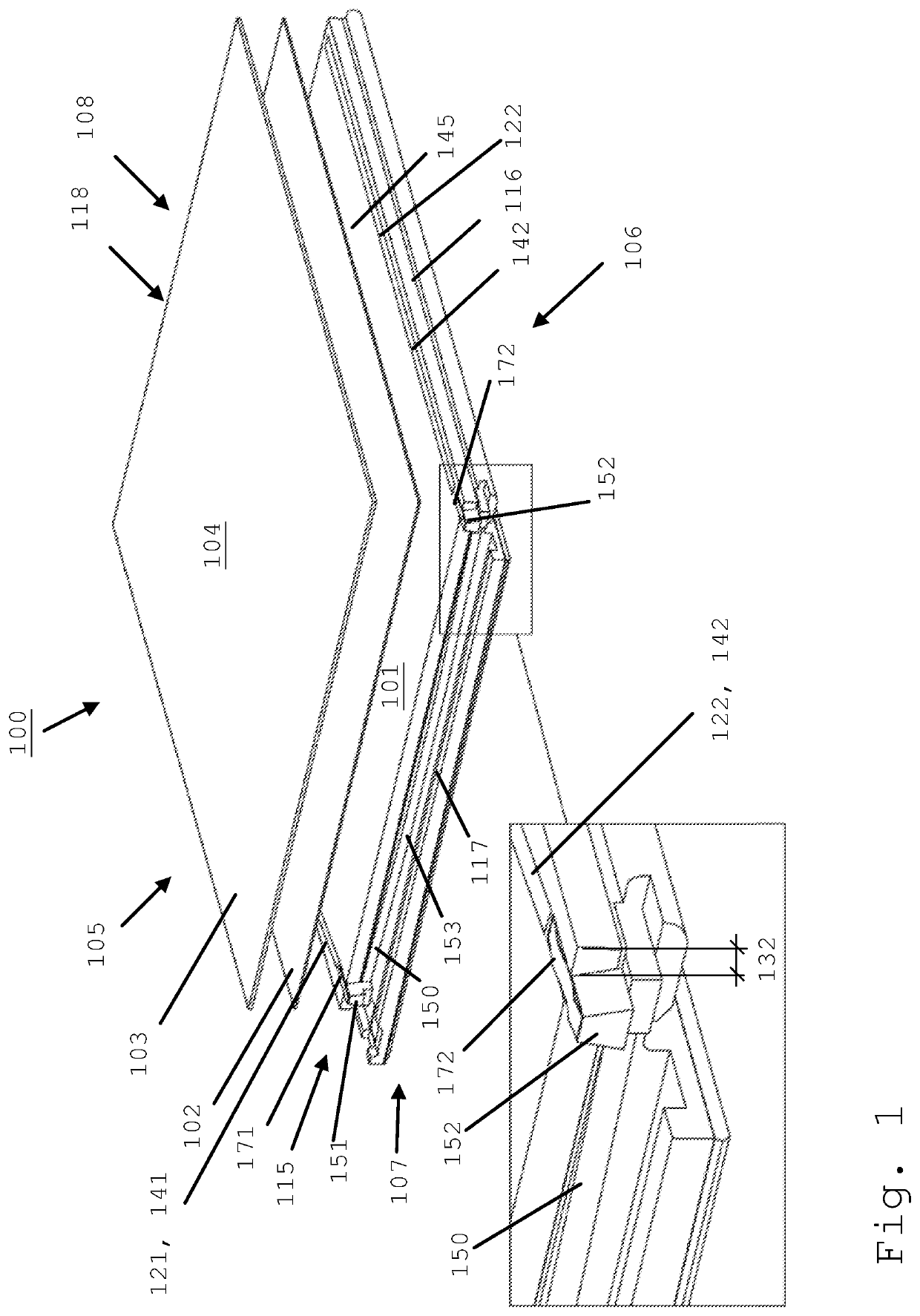
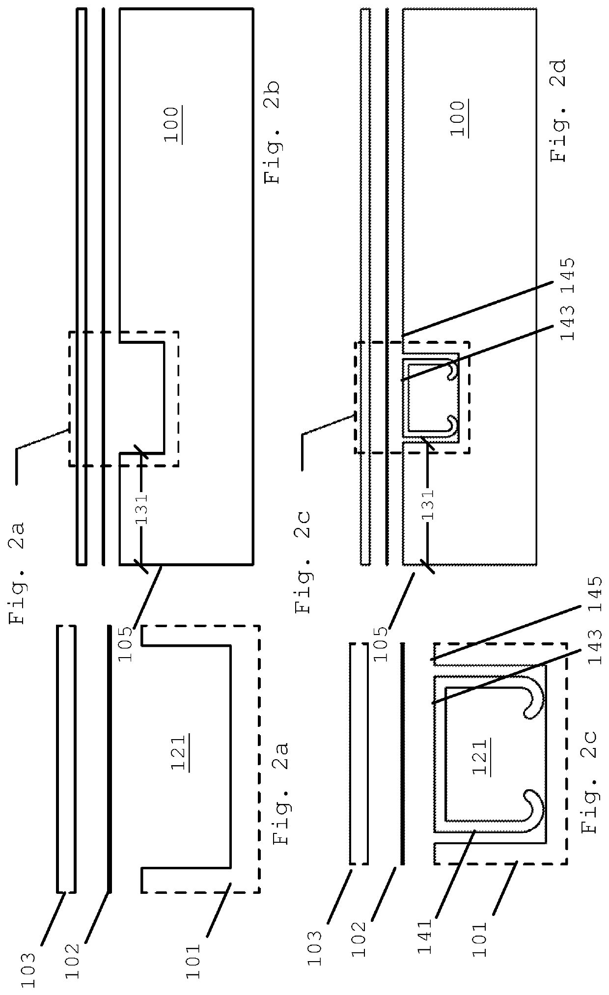
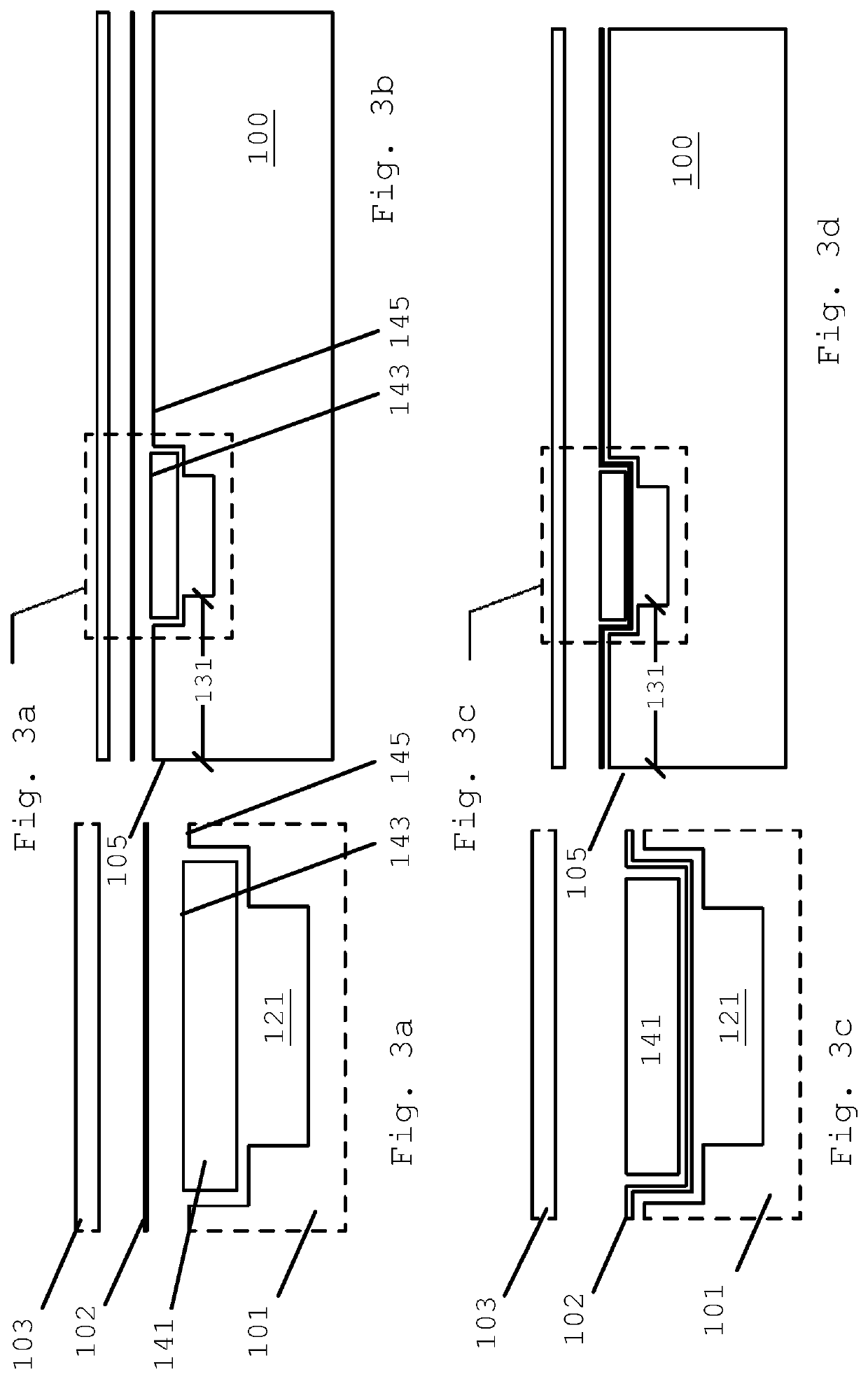
[0066]FIGS. 1, 2a-d, 3a-d, 4a-d, and 5a-k schematically show views of a panel 100 and / or an electrical end connector 150 according to various embodiments of the present invention.

[0067]As is shown e.g. in FIG. 1, the panel 100 is delimited by a first longitudinal side 105 and by a second longitudinal side 106 being opposite the first longitudinal side 105. The panel 100 is also delimited by a first end side 107 and by a second end side 108 being opposite the first end side 107.

[0068]The first longitudinal side 105, the second longitudinal side 106, the first end side 107, and the second end side 108 may be provided with panel coupling means, such as a groove / female and tongue / rabbet forming e.g. “click joints”115, 116, 117, 118, respectively. The panel coupling means 115, 116, 117, 118 are, according to an embodiment, arranged in the base layer 101 at the first 105 and second 106 longitudinal sides of the panel, and at the first 107 and second 108 end sides of the panel, for mechani...


PUM

PropertyMeasurementUnit
voltagesaaaaaaaaaa
voltagesaaaaaaaaaa
voltagesaaaaaaaaaa

Abstract

A panel comprising a heat providing layer is presented. The panel includes panel coupling means arranged for coupling the panel to adjacent panels. Longitudinal grooves are arranged in the panel along the whole length of the panel. In order to provide heat, at least one electrical end connector is arranged at one or more end panel coupling means. The electrical end connectors are arranged for being electrically connected to the heat providing layer, for being at least partly electrically conductive, and for at least partly protruding from the one or more end panel coupling means, thereby providing an electrical connection between the heat providing layer of the panel and a corresponding heat providing layer of at least one adjacent panel coupled to the panel. The invention also concerns a heating system comprising such a panel, the electrical end connector, and a method for installing such a heating system.

Description

FIELD OF INVENTION[0001]The present invention relates to a panel as defined in the preamble of claim 1. The present invention also relates to an electrical end connector as defined in the preamble of claim 31. The present invention also relates to a heating system as defined in the preamble of claim 32. The present invention also relates to a method for installing a heating system as defined in claim 36.BACKGROUND OF INVENTION[0002]The following background information is a description of the background of the present invention, which thus not necessarily has to be a description of prior art.[0003]One of our times big challenges is to reduce the overall energy consumption in the world. In many parts of the world, houses, apartments, offices, shops, factories and / or other public or non-public spaces, need to be heated in order to provide an acceptable environment for people spending time in these spaces. Such heating thus needs to provide a comfortable temperature at the same time as ...

Claims


Application Information

Patent Timeline
Patent Type & Authority Applications(United States)
IPC IPC(8): F24D13/02E04F15/02E04F15/10
CPCE04F2201/023E04F15/107E04F2201/0107H05B3/26E04F15/02038F24D13/024E04F2201/0146E04F2201/0547Y02B30/00E04F2290/023E04F2201/0176H05B3/06H05B2203/016H05B2203/026
Inventor NYSTRÖM, TAISTO KALEVILÖFHOLM, HÅKAN JOHAN
Owner HEAT CLICK CO AB
Why Eureka
Try Eureka