
Dynamic Silk Coatings for Implantable Devices

a technology of implantable devices and silk coatings, which is applied in the field of silk-based implantable systems and devices, can solve the problems of long-term reliability of chronic cortical electrode implants, lack of chronic reliability, and loss of the ability to record neurons, so as to improve the compliance and shorten the life of the electrode and the implant. the effect of the loss of function

Active Publication Date: 2020-04-09
TRUSTEES OF TUFTS COLLEGE
View PDF0 Cites 1 Cited by
  • Summary
  • Abstract
  • Description
  • Claims
  • Application Information

AI Technical Summary

Benefits of technology

The patent text discusses the challenge of creating a neural recoding interface because flexible electrodes cannot penetrate into brain tissue and erosion of connections between abiotic and biotic niches results in a loss of function of electrodes and implants. The text presents a solution in the form of dynamic silk coatings that can be applied onto flexible devices before or after implantation. The silk coating provides mechanical strength to the device before implantation and softens upon insertion into brain tissue. It can also be renewably formed in situ on the surface of the device after implantation to minimize bio-fouling. Overall, this approach allows for the development of implantable devices and systems with sufficient mechanical stiffness for insertion into brain tissue without compromising their mechanical compliance with brain tissue afterward.

Problems solved by technology

Despite this success, the long-term reliability of chronic cortical electrode implants remains a major obstacle to the widespread adaptation of neuroprosthetic technologies to the clinic, with many penetrating arrays losing the ability to record neurons after just weeks or months.
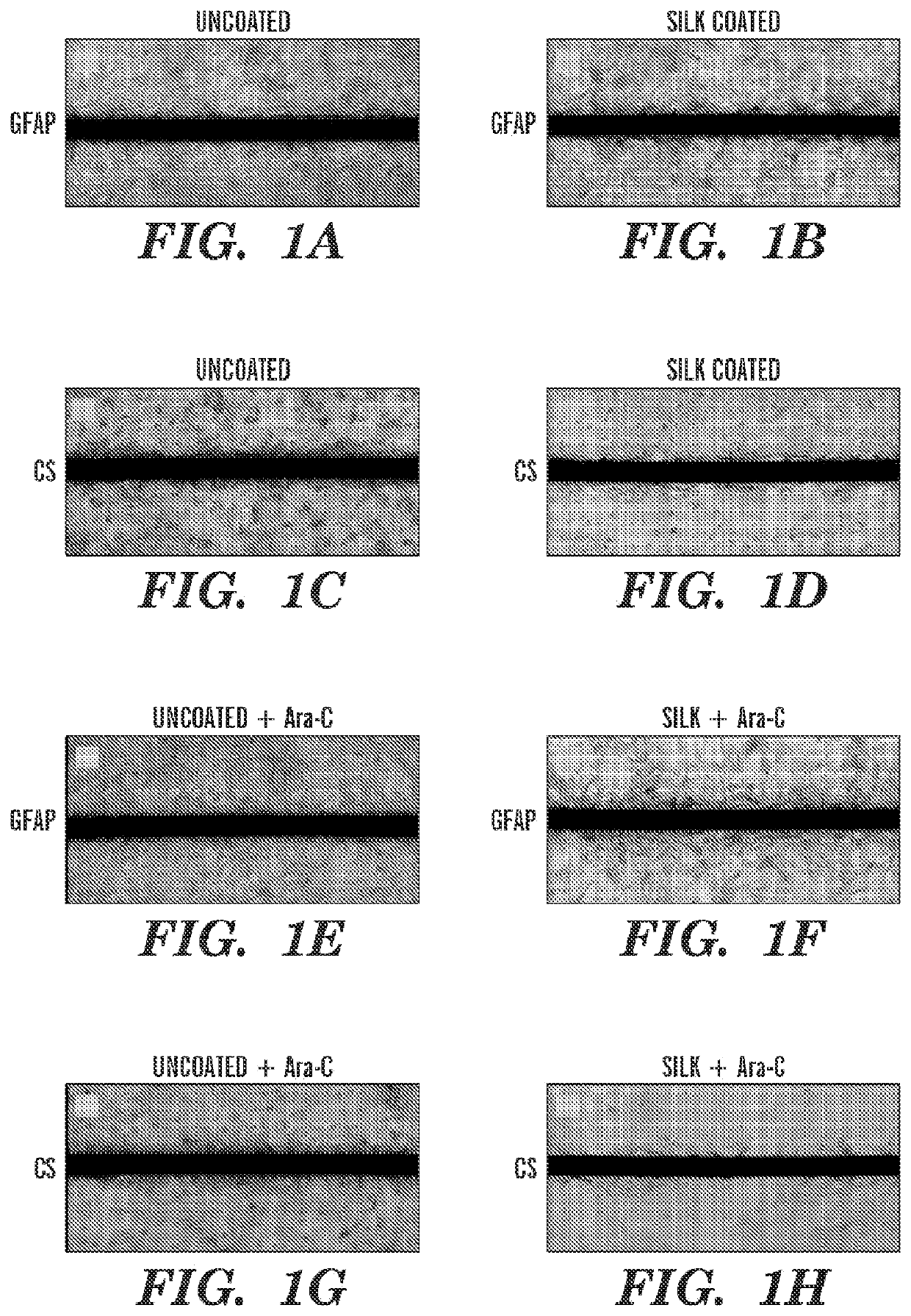
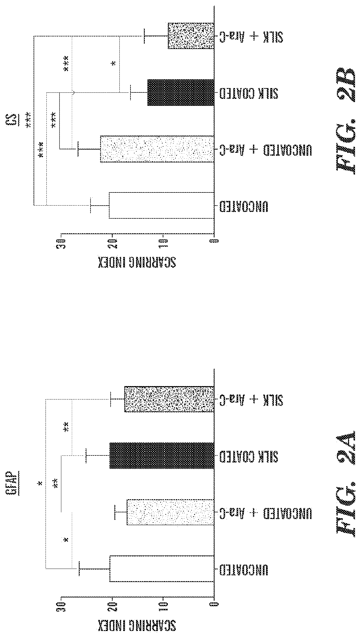
This lack of chronic reliability is often attributed to gliosis, the inflammatory response in the central nervous system.
As the glial scar grows, the electrode becomes incapable of recording extracellular action potentials.
However, continuing to extract signals with a high fidelity over long periods of time remains a major challenge.
Presently, issues regarding electrode fracture and signal drop-out plague metal-based micro-electrodes for long-term use.
Rigid metal needles do not comply mechanically with brain tissue, shifting during normal head movement, resulting in electrode misplacement from the target neural tissue area and electrode breaks.
Electrode micromotion resulting from a mismatch in stiffness between the electrode and the brain tissue leading to chronic inflammation and associated increased glial activation, and movement of the electrode from the target, resulting in inconsistent readings.
Such flexible probes introduce an additional challenge, however, as these devices can be incapable of penetrating the pia to achieve precise insertion into the brain without buckling.
Further, the neural recording interface remains another major challenge.
Erosion of connections between the abiotic and biotic niches results in loss of function of electrodes and implants.
This is an endemic problem in biology and one that has resisted traditional approaches for resolution.
As a result, implants for recording electronics have relatively short lifetimes, requiring constant replacement, leading to associated failure modes due to the device itself or repeated surgical intervention that damages surrounding tissue.
Since most electrode implants remain relatively rigid and damaging upon insertion, the interface between current systems and the dynamic nature of biological systems tend to be a major source of problems.
The dynamic issues include the biochemistry at the site (cell signaling factors, ECM deposition), cell dynamics at the site (e.g., astroglial and other nerve cells that respond to and with the implants), and stress shielding (e.g., mechanical mismatch between electrodes and soft brain tissue, leading to failure modes, fibrous encapsulation and related complications and failures to maintain a stable interface).
Further, a related underlying problem includes the limited ability to establish a conformal and tight interface, due to the mechanical mismatch, between the existing materials and the soft and convoluted brain and neurological tissues.
The neural recoding interface remains a major challenge.
While flexible electrodes are desired to be used for their better compliance with a brain tissue, these flexible electrodes are not stiff enough to penetrate into a brain tissue.
Further, erosion of connections between the abiotic and biotic niches results in a loss of function of electrodes and implants.
As a result, implants (e.g., for recoding electronics) have relatively short lifetimes, thus requiring constant replacement and leading to associated failure modes due to the device itself or repeated surgical intervention that damages surrounding tissue.

Method used


Image

  • Dynamic Silk Coatings for Implantable Devices
  • Dynamic Silk Coatings for Implantable Devices
  • Dynamic Silk Coatings for Implantable Devices

Examples


example 1

Materials and Methods

[0280]Preparation of Silk Solution.

[0281]Silk solution was prepared from Bombyx mori silkworm cocoons according to the procedures described in previously-reported studies (35-37). Cocoons of B. mori silkworm silk were supplied by Tajima Shoji Co. (Yokohama, Japan). Briefly, the cocoons were degummed in a boiling 0.020□M Na2CO3 (Sigma-Aldrich, St. Louis, Mo.) solution for 15 min. The fibroin extract was then rinsed three times in Milli-Q water, dissolved in a 9.3M LiBr solution yielding a 20% w / v solution, and subsequently dialyzed (MWCO 3,500 kDa) against distilled water for 2 days to obtain regenerated aqueous silk fibroin solution (ca. 8% w / v). The silk solution was concentrated to 15% w / v by dialysis overnight.

[0282]Fabrication of Electrodes.

[0283]Flexible electrodes (e.g., flexible cortical electrodes) could be fabricated by any standard MEMS fabrication techniques known in the art. In some embodiments, any art-recognized flexible electrodes can be used in t...

example 2

Coating of Flexible Neural Probes with Silk Fibroin

[0312]A layer-by-layer casting technique was used to coat a flexible electrode, e.g., a polyimide-based thin film neural probe) with silk fibroin. The probes were first centered, with electrode recording sites facing down, on PDMS molds that were fabricated using a laser cutter or soft lithography techniques. The shape of the PDMS mold can vary with the shape and / size of the electrode. The PDMS mold can partly determine the silk-coated electrode shank dimensions. Concentrated silk solution (15% w / v) was applied to the molds, e.g., by drawing a bead of solution from the tip of a pin head along the length of the probe shank. The draw speed and viscosity of the silk solution, as well as the mold shape, determined the amount of solution that adhered to the mold and probe. After drying, successive layers of silk were applied in the same manner in order to increase the thickness of the coating. Despite the manual nature of this coating te...

example 3

l Properties of Silk-Coated Probes

[0315]Uncoated, 3-layer, and 6-layer silk-coated probes can be mechanically characterized by driving the probes perpendicularly onto a precision analytical balance at a rate of about 0.5 mm / min. Without wishing to be bound by theory, there can be an initial linear increase in force while the probes remain straight before buckling. As the probes continue to be driven onto the balance, the shanks can begin to buckle and bend. This can be characterized by the peak and gradual decrease in force. Eventually, the silk coating on the 3 and 6 layer probes can fracture midway down the shank, which can be characterized by a sharp decrease in force exerted on the balance.

[0316]For practical in vivo applications, neural probes are desired to remain straight during insertion in order to reach a precisely targeted region of the brain. Therefore, the buckling force should not be exceeded during insertion through the pia mater and into the cortex. The average buckl...


PUM


Abstract

Provided herein relates to implantable devices and systems with dynamic silk coatings. In some embodiments, the dynamic silk coatings can be formed in situ or in vivo.

Description

CROSS-REFERENCE TO RELATED APPLICATIONS[0001]This application claims benefit under 35 U.S.C. § 119(e) of the U.S. Provisional Application No. 61 / 477,484, filed Apr. 20, 2011, the content of which is incorporated herein by reference in its entirety.GOVERNMENT SUPPORT[0002]This invention was made with government support under grant no. P41 EB002520 awarded by the National Institutes of Health (NIH). The government has certain rights in the invention.FIELD OF THE DISCLOSURE[0003]Provided herein relates to silk-based implantable systems and devices and methods of preparing the same. In some embodiments, the silk-based implantable systems and devices can be adapted for use as neuroprosthetic devices such as brain electrodes, shunts and / or spinal cord nerve guide wires.BACKGROUND OF THE DISCLOSURE[0004]Neuroprosthetic devices hold promise for future biomedical human-machine interactions. Various applications of this technology are actively being explored, ranging from direct neural contro...

Claims


Application Information

Patent Timeline
Patent Type & Authority Applications(United States)
IPC IPC(8): A61L31/10A61L31/16A61N1/05A61L31/14A61L31/04A61L27/36A61L27/22A61B5/00A61B5/0478
CPCA61L31/14A61B5/0478A61B5/686A61B5/4088A61N1/375A61N1/0541A61B5/6868A61N1/0529A61L27/3675A61N1/05A61L2400/18A61B5/4094A61L27/227A61L31/047A61L2420/06A61L31/10A61B2562/125A61L31/16A61L27/3604A61B5/6877A61B5/291A61B5/293A61B5/27
Inventor KAPLAN, DAVID L.TIEN, LEE W.LEISK, GARY G.LO, TIM JIA-CHINGMETALLO, CINZIAOMENETTO, FIORENZO
Owner TRUSTEES OF TUFTS COLLEGE
Learn More