Air flow controller and manufacturing method of stretched film
- Summary
- Abstract
- Description
- Claims
- Application Information
AI Technical Summary
Benefits of technology
Problems solved by technology
Method used
Image


Examples
embodiment
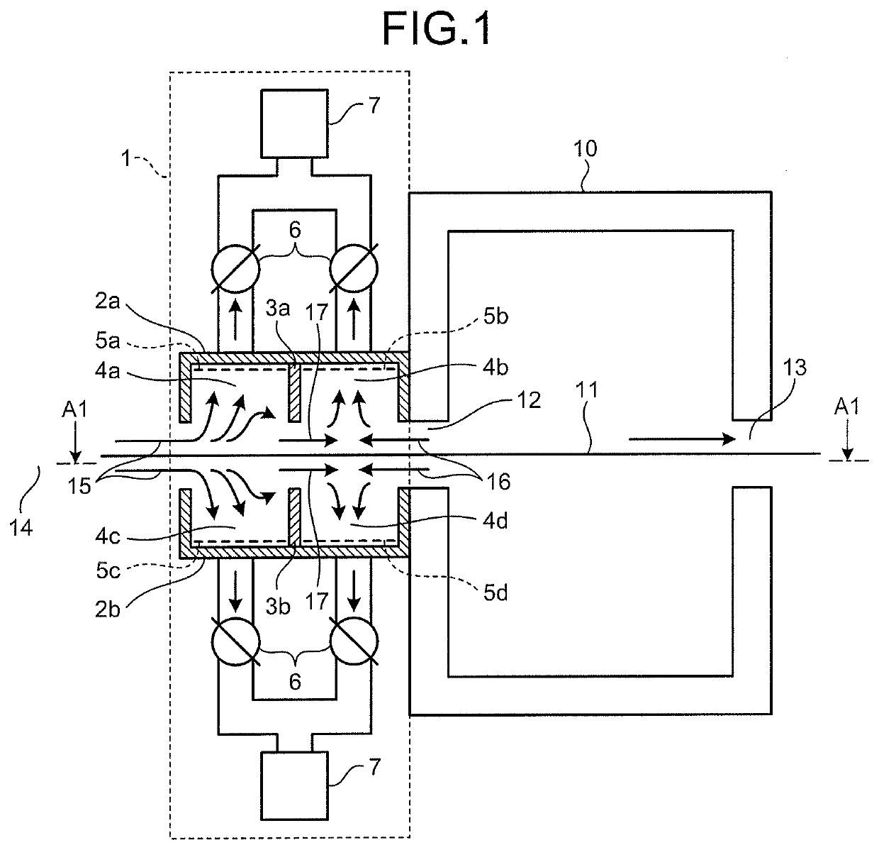
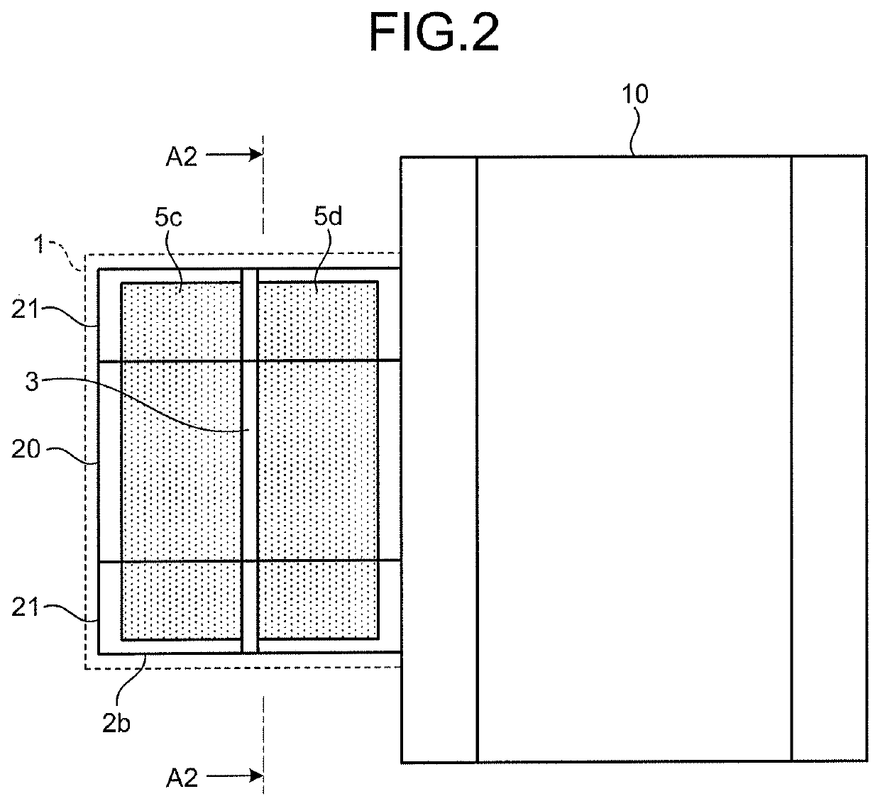
[0043]An air flow controller according to an embodiment of the present invention is described with reference to FIGS. 1 and 2. FIG. 1 is a schematic cross-sectional view of the air flow controller according to the embodiment of the present invention in a film running direction. FIG. 1 is a cross-sectional view of the air flow controller by being cut with a plane perpendicular to a film running surface. FIG. 2 is a schematic cross-sectional view of the air flow controller taken along line A1-A1 illustrated in FIG. 1. A tenter oven 10 produces a stretched film by stretching an unstretched film in a uniaxial direction or two directions different from each other while the unstretched film is heated at a certain temperature. The unstretched film is gripped by clips, which are described later, and disposed on a film running surface 11. The unstretched film runs on the film running surface 11 by being stretched with the clips running on clip rails.
[0044]A thermoplastic resin film is exempl...
examples
[0067]The following describes the present invention in detail by examples. The present invention is not limitedly interpreted by the following examples.
first example
[0068]An evaluation method of an effect of the present invention is described. A numerical analysis model modeling the air flow controller according to the present invention and the chambers included in the tenter oven body was created. An air flow control performance was evaluated by numerically calculating the numerical analysis model.
[0069]FIG. 6 is a cross-sectional view in the film running direction of the air flow controller used in the examples of the present invention. FIG. 6 is a cross-sectional view of the air flow controller 1 and the tenter oven 10 by being cut with a plane perpendicular to the film running surface 11. FIG. 6 illustrates the structure of an upper half of the air flow controller 1 and the tenter oven 10 out of upper and lower portions separated by the film running surface 11 as the separation boundary. In calculating internal air flows in the air flow controller 1 and the tenter oven 10, the air flow controller 1, the tenter oven 10, and the external spac...
PUM
| Property | Measurement | Unit |
|---|---|---|
| Flow rate | aaaaa | aaaaa |
| Width | aaaaa | aaaaa |
Abstract
Description
Claims
Application Information
 - Generate Ideas
- Intellectual Property
- Life Sciences
- Materials
- Tech Scout
- Unparalleled Data Quality
- Higher Quality Content
- 60% Fewer Hallucinations
Browse by: Latest US Patents, China's latest patents, Technical Efficacy Thesaurus, Application Domain, Technology Topic, Popular Technical Reports.
© 2025 PatSnap. All rights reserved.Legal|Privacy policy|Modern Slavery Act Transparency Statement|Sitemap|About US| Contact US: help@patsnap.com