Electric bus with seats over driving wheels

a technology of electric buses and seats, applied in the field of electric buses, can solve the problems of increasing the weight and overall dimensions, affecting the cost of driven kilometres pro passenger, and the circulation in cities exposes electric buses to accidents with other vehicles, so as to reduce the height increase the compactness of the electric bus, and reduce the diameter

Active Publication Date: 2020-04-09
ALPHA EC IND 2018 S A R L
View PDF19 Cites 1 Cited by
  • Summary
  • Abstract
  • Description
  • Claims
  • Application Information

AI Technical Summary

Benefits of technology

[0099]The different aspects of the invention may be combined to each other. In addition, the preferable options of each object of the invention may be combined with the other objects of the invention, unless the contrary is explicitly mentioned.
[0100]It may be understood that the invention provides an electric bus exhibiting a thin low platform and small wheels, which are however involved in side protection. More specifically, the invention provides a specific vertical positioning of the stiff portions of a wheel with respect to the main platform receiving passengers. It will be understood that a low platform increases the compactness of an electric bus, and favours a no-step docking along a street curb stone at a bus stop. The height of the electric bus may be reduced significantly while keeping a comfortable space within the passenger compartment.

Problems solved by technology

However, keeping a high passenger capacity generally requires to increase the weight and the overall dimensions.
In turn, these compromises generally impact the cost of driven kilometre pro passenger.
Indeed, circulation in cities exposes electric busses to accidents with other vehicles.
Since the seated passengers occupying the longitudinal seat rows are directly behind this side wall, they are directly exposed to injuries.

Method used


Image

  • Electric bus with seats over driving wheels
  • Electric bus with seats over driving wheels
  • Electric bus with seats over driving wheels

Examples


Embodiment Construction

[0108]This section describes the invention in further detail based on preferred embodiments and on the figures. Similar reference numbers will be used to describe similar or the same concepts throughout different embodiments of the invention.

[0109]It should be noted that features described for a specific embodiment described herein may be combined with the features of other embodiments unless the contrary is explicitly mentioned.

[0110]Features commonly known in the art will not be explicitly mentioned for the sake of focusing on the features that are specific to the invention. For example, the electric bus in accordance with the invention is evidently equipped with a computer, even though such computer is not explicitly referenced on the figures nor referenced in the description.

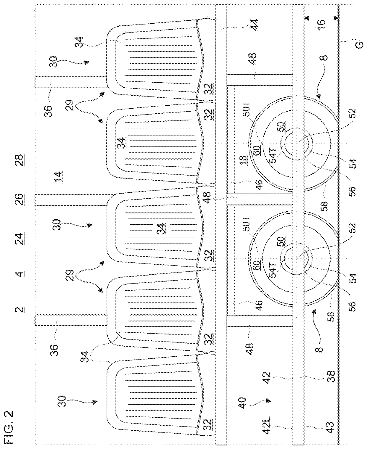
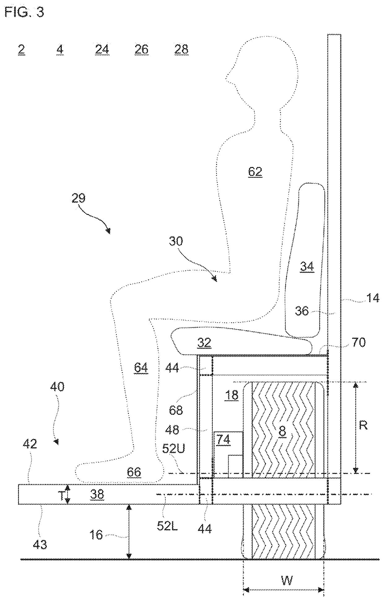
[0111]The dimensions may be measured free of passengers, and / or on a horizontal planar ground.

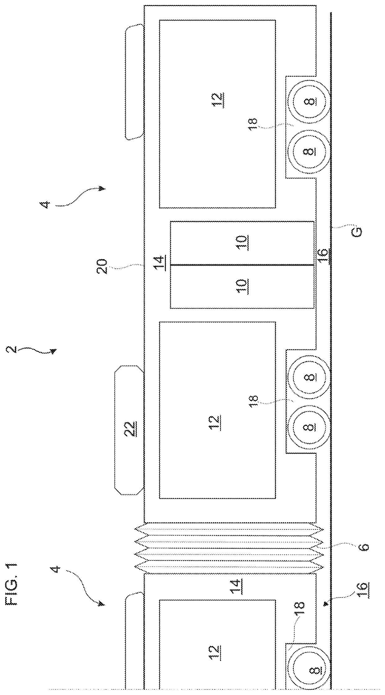
[0112]In the following description, the word “longitudinal” may correspond to the main elongation of the electric...


PUM


Abstract

An articulated electric bus includes two units with: a passenger compartment including a main floor forming a low and thin platform with a planar surface extending over the majority of the width of the passenger compartment, a wheel housing adjacent to the planar surface, a longitudinal row of seat places on the wheel housing, and a driving wheel which is housed in the wheel housing under the longitudinal row of seats. The driving wheel defines a rotation axis and includes an electric engine, and a rim with a rim top above the planar surface. The driving wheel is vertically movable with respect to the planar surface, and the wheel housing actually receives a pair or a couple of driving wheels.

Description

TECHNICAL FIELD[0001]The invention stands in the field of electric bus. More precisely, the invention provides a passenger compartment architecture for an electric bus. The invention provides safety solutions adapted for an electric, notably with regard to side collision.BACKGROUND OF THE INVENTION[0002]An electric bus combines a passenger compartment with longitudinal seat rows, and wheel housings protruding within the passenger compartment. Arranging the longitudinal seat rows alongside side walls permits to keep a wide platform for standing passengers therebetween.[0003]Consequently, this arrangement increases the overall passenger capacity of the electric bus, notably of its tractor and of its there attached trailers.[0004]In order to promote the autonomy by means of an energy consumption reduction, the weight and the overall dimensions of the electric bus are reduced. However, keeping a high passenger capacity generally requires to increase the weight and the overall dimensions...

Claims


Application Information

Patent Timeline
Patent Type & Authority Applications(United States)
IPC IPC(8): B62D47/02B60D5/00B60K1/02B60K1/04
CPCB60K1/04B60K2001/0438B60L2200/18B60D5/003B60K1/02B62D47/025B60N2/242B60K7/0007B60Y2200/14B60Y2200/143B60Y2200/1432B62D31/02
Inventor HALLUNDBÆK, JØRGEN
Owner ALPHA EC IND 2018 S A R L
Why Eureka
Try Eureka