
Aerodynamic cover of vehicle

a technology of aerodynamic cover and vehicle, which is applied in the direction of pivoted suspension arms, transportation and packaging, road transportation emission reduction, etc., can solve the problems of reducing the time required for installing the aerodynamic cover, the aerodynamic cover may not be kept in a stably installed condition, and the engaging portion may become prone to slipping, so as to reduce the air resistance and protect the suspension device, the rigidity of the aerodynamic cover is kept high, and the other horizontal portion is kept rigid

Active Publication Date: 2020-04-16
TOYOTA JIDOSHA KK
View PDF0 Cites 1 Cited by
  • Summary
  • Abstract
  • Description
  • Claims
  • Application Information

AI Technical Summary

Benefits of technology

The patent describes an aerodynamic cover for a suspension device that reduces wear and tear, reduces air resistance, and provides a stabile installed condition. The cover has a reduced number of bolting locations and a decreased length of time required for installation. The cover includes an engaging portion on one horizontal portion that engages with the arm member of the suspension device, and a bolt receiving portion on another horizontal portion that is bolted to the arm member. The engaging portion has a rib that increases the strength of the arm portion, ensuring a stable engagement with the arm member. The cover also includes a bolt receiving portion that prevents the surface from wearing down, maintaining the rigidity of the aerodynamic cover and its effects. Overall, the patent provides a solution for improving the efficiency and durability of aerodynamic covers for suspension devices.

Problems solved by technology

Since some work time is required for the bolt screwing operation, there is a limitation to reduction of the time required for installing the aerodynamic cover, due to the presence of the two or more bolting locations.
In this case, however, the engaging portion may become worn due to sliding motion of the engaging portion and the arm member relative to each other, which is caused by vibration, etc. of the vehicle, and the aerodynamic cover may not be kept in a stably installed condition.
Since the bolt receiving portion protrudes in the vertical direction from the surface of the other horizontal portion opposite to the arm member, the head portion of the bolt is less likely or unlikely to contact with the surface of the other horizontal portion, even in a situation where the head portion of the bolt presses the seating face (end face of the bolt receiving portion) and causes the seating face to wear, due to fastening force applied when the bolt is fastened.

Method used


Image

  • Aerodynamic cover of vehicle
  • Aerodynamic cover of vehicle
  • Aerodynamic cover of vehicle

Examples


Embodiment Construction

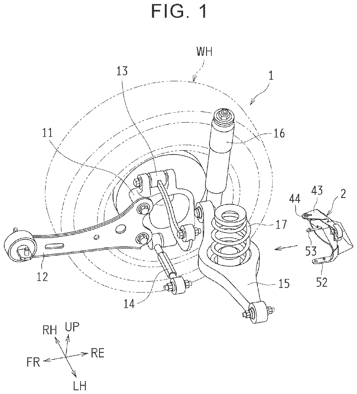
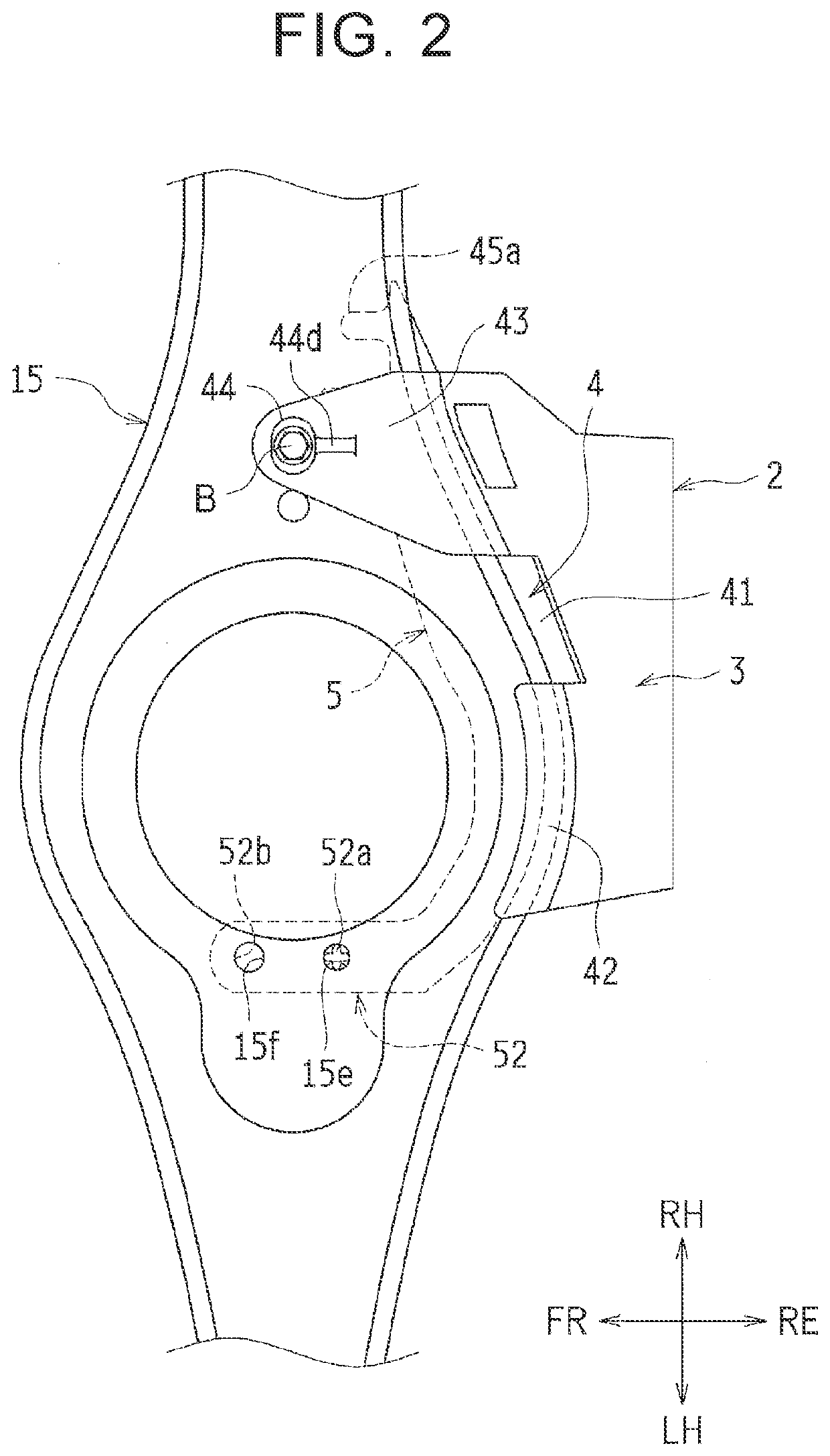
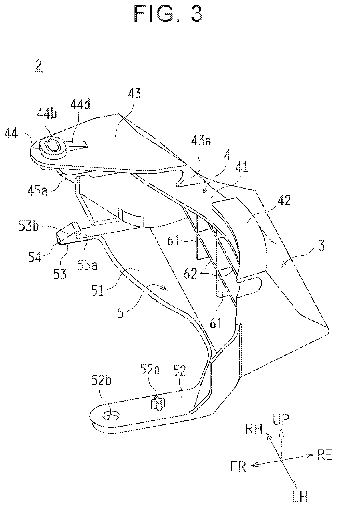
[0027]One embodiment will be described based on the drawings. In this embodiment, the disclosure is applied to an aerodynamic cover mounted on a second lower arm of a suspension device that suspends a rear wheel of a vehicle.

[0028]The structure of the suspension device will be generally described, before the structure of the aerodynamic cover and installation of the aerodynamic cover are described.

[0029]Structure of Suspension Device

[0030]FIG. 1 is a perspective view useful for describing a direction in which an aerodynamic cover (which will also be called “lower cover”) 2 is mounted on a suspension device 1 in this embodiment. The suspension device 1 shown in FIG. 1 is used for suspending a right, rear wheel WH (indicated by virtual lines in FIG. 1) of the vehicle. A suspension device for suspending a left, rear wheel of the vehicle, which is not illustrated herein, has a symmetric structure with respect to the suspension device 1 for suspending the right, rear wheel WH. In FIG. 1,...


PUM


Abstract

An aerodynamic cover of a suspension device of a vehicle includes an upper horizontal portion that is located on an upper side of the arm member and extends in a horizontal direction, a lower horizontal portion that is located under the arm member and extends in the horizontal direction, an engaging portion that is provided on one of the upper and lower horizontal portions and engaged with the arm member, and a bolt receiving portion that is provided on the other horizontal portion and bolted to the arm member. The engaging portion includes an arm portion extending in the horizontal direction, and a claw portion provided on a distal side of the arm portion and engaged with the arm member. A rib provided on the arm portion extends in a direction of extension of the arm portion, and protrudes in a vertical direction with respect to the arm portion.

Description

INCORPORATION BY REFERENCE[0001]The disclosure of Japanese Patent Application No. 2018-193990 filed on Oct. 15, 2018 including the specification, drawings and abstract is incorporated herein by reference in its entirety.BACKGROUND1. Technical Field[0002]The disclosure relates to an aerodynamic cover of a vehicle. In particular, the disclosure is concerned with an improvement of the structure of the aerodynamic cover mounted on an arm member of a suspension device.2. Description of Related Art[0003]As disclosed in Japanese Unexamined Patent Application Publication No. 2009-196557 (JP 2009-196557 A), an aerodynamic cover (which is called “lower cover” in JP 2009-196557 A) is known which is mounted on an arm member (which is called “lower arm” in JP 2009-196557 A) of a suspension device of a vehicle. The aerodynamic cover is provided for reducing air resistance (traveling resistance) and improving the fuel consumption rate by regulating air that flows under the vehicle (under a floor) ...

Claims


Application Information

Patent Timeline
IPC IPC(8): B62D35/02B60G3/10
CPCB62D35/02B60G2204/4308B60G3/10B60G2204/20B60G7/00Y02T10/88B60G3/20B60G2200/182B60G7/001
Inventor KITASHIBA, SHUNSUKEYOKOZAWA, YASUYUKITOMITA, TAKASHIKAWANISHI, SEIICHIRO
Owner TOYOTA JIDOSHA KK
Learn More