Method for constructing natural gas liquefaction plant

a technology of natural gas liquefaction and liquefaction plant, which is applied in the direction of liquefaction, machine operation mode, lighting and heating apparatus, etc., can solve the problems of requiring a longer time before refrigerant compression module, and the entire construction period becomes longer, so as to achieve the effect of shortening the time period required for constructing a natural gas liquefaction plan

Active Publication Date: 2020-04-16
CHIYODA CORP
View PDF0 Cites 2 Cited by
  • Summary
  • Abstract
  • Description
  • Claims
  • Application Information

AI Technical Summary

Benefits of technology

[0022]According to the present invention, a time period required for constructing a natural gas liquefaction plant can be shortened by achieving the above-described technical effects.

Problems solved by technology

However, as a refrigerant compressor mounted in the refrigerant compression module tends to have a longer lead time compared to the other equipment and apparatuses included therein, the method, in which the refrigerant compressor is mounted in the module at a place remote from a construction site before the assembled module is transported to the construction site, requires a longer time before the refrigerant compression module can be transported to the construction site due to a longer lead time of the refrigerant compressor.
As a result, an entire construction period also becomes longer.

Method used


Image

  • Method for constructing natural gas liquefaction plant
  • Method for constructing natural gas liquefaction plant
  • Method for constructing natural gas liquefaction plant

Examples


Embodiment Construction

)

[0033]Embodiments of the present invention are described in the following with reference to the appended drawings.

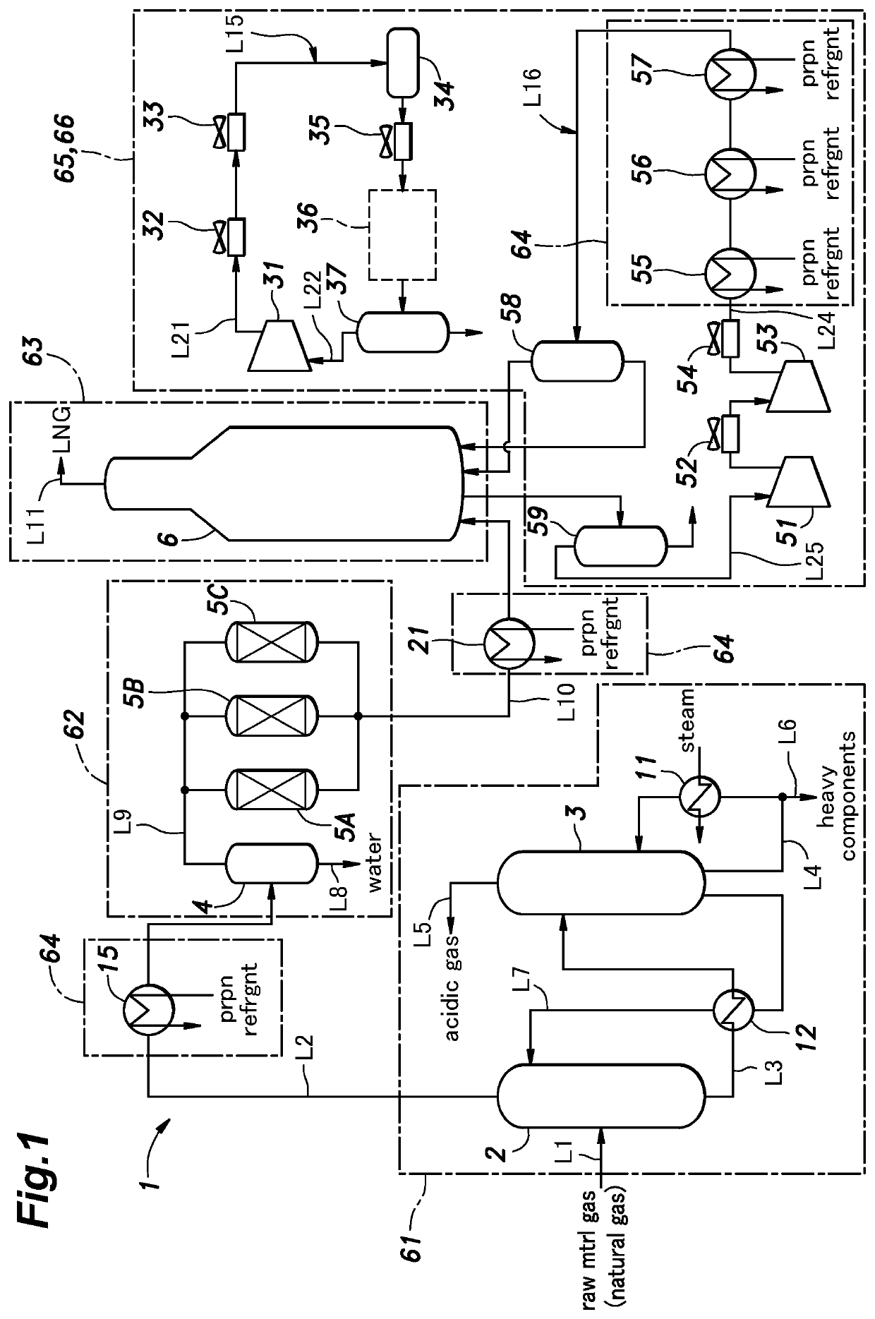
[0034]FIG. 1 is a schematic diagram showing a general configuration of a natural gas liquefaction plant (hereafter also referred to as “LNG plant”) 1 in accordance with one embodiment of the present invention. In FIG. 1, each pipe for transporting a raw material gas or any other fluid is schematically shown by a line including an arrow.

[0035]The LNG plant 1 includes multiple facilities for producing a liquefied natural gas (LNG) by cooling a raw material gas. The LNG plant 1 includes an absorption tower 2 for removing acidic gas contained in the raw material gas, a regeneration tower 3 for regenerating an absorbent used in the absorption tower 2, a gas-liquid separator 4 for performing gas-liquid separation in order to separate moisture from the raw material gas, moisture removers 5A to 5C for removing moisture contained in the raw material gas, and a liquefier 6 for li...


PUM


Abstract

Provided is a method of constructing a natural gas liquefaction plant, which can shorten a construction time period by minimizing effect of a lead time for the refrigerant compressor thereon, the method including: transporting a refrigerant compression module body 175 to an installation area 85, wherein the refrigerant compression module body is provided with a frame 120 configured to allow refrigerant compressor 150 for compressing a refrigerant for cooling natural gas to be mounted therein; installing the refrigerant compression module body 175 to the installation area 85; and mounting the refrigerant compressor 150 into a mounting space 130 predefined in the frame 120 of the installed refrigerant compression module body.

Description

TECHNICAL FIELD[0001]The present invention relates to a method for constructing a natural gas liquefaction plant including one or more modularized facilities.BACKGROUND ART[0002]In construction methods of the prior art, one example is a method for constructing a natural gas liquefaction plant (hereafter also referred to as “LNG plant”) involves the step of assembling necessary facilities at a construction site, where the necessary facilities include an acidic gas removing facility for removing acidic gases contained in a raw material gas to be subjected to a liquefaction, a moisture removal facility for removing moisture contained in the raw material gas, and compression equipment for compressing a refrigerant (such as mixed refrigerant or propane refrigerant) used for cooling and liquefying the raw material gas.[0003]One of known techniques for promoting efficiency of the above-described construction work performed a construction site is a method including the steps of: assembling ...

Claims


Application Information

Patent Timeline
Patent Type & Authority Applications(United States)
IPC IPC(8): F25J1/02F25J1/00
CPCF25J1/0257F25J1/0259F25J1/0022F25B27/02F25B31/00F25J1/0052F25J1/0055F25J1/0087F25J1/0216F25J1/0296F25J1/0292F25J2290/42
Inventor KOBAYASHI, KENICHIKAJI, TAKESHIYAMAGATA, MAKOTO
Owner CHIYODA CORP
Why Eureka
Try Eureka