Cooling device with controllable evaporation temperature

a cooling device and controllable technology, applied in the field of cooling devices, can solve the problems of complex logistics for the provision or generation and storage of liquefied gases, the inability to adjust the throttle, and the resultant very cold temperature of the adjustable throttle, so as to achieve simple and yet effective effects

Inactive Publication Date: 2012-09-27
BRUKER BIOSPIN
View PDF6 Cites 1 Cited by
  • Summary
  • Abstract
  • Description
  • Claims
  • Application Information

AI Technical Summary

Benefits of technology

[0010]This object is achieved in a surprisingly simple and yet effective fashion in that an additional relief throttle is arranged between the evaporator of the last cascade cooling stage and the compressor of the last cascade cooling stage.

Problems solved by technology

Provision or generation and storage of these liquefied gases requires complex logistics.
Such a configuration is technically complex when the cycle process to be varied is already operated in a cascade of cycle processes at a very low liquefaction temperature and the adjustable throttle consequently also becomes very cold.

Method used


Image

  • Cooling device with controllable evaporation temperature
  • Cooling device with controllable evaporation temperature

Examples


Embodiment Construction

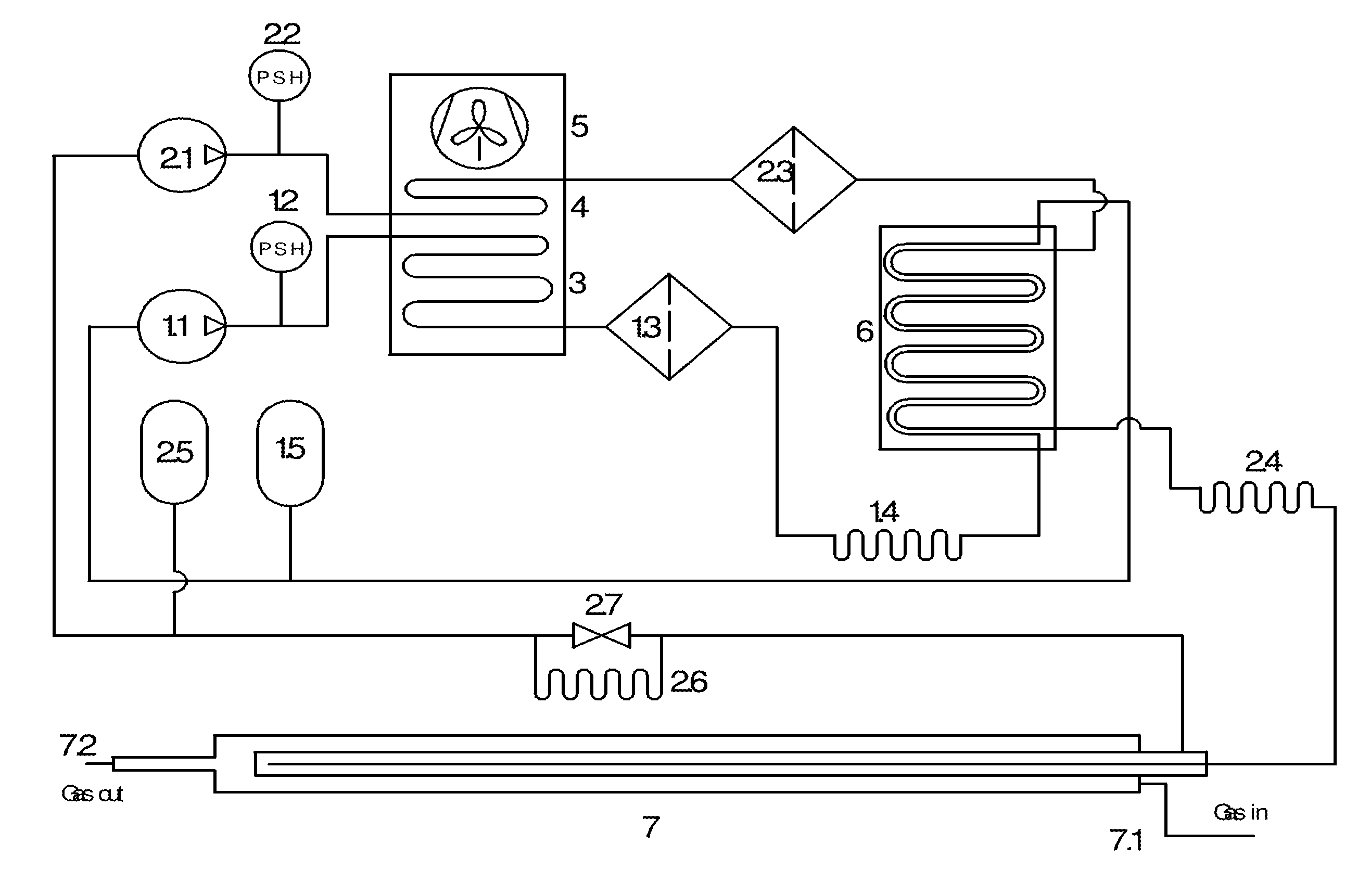
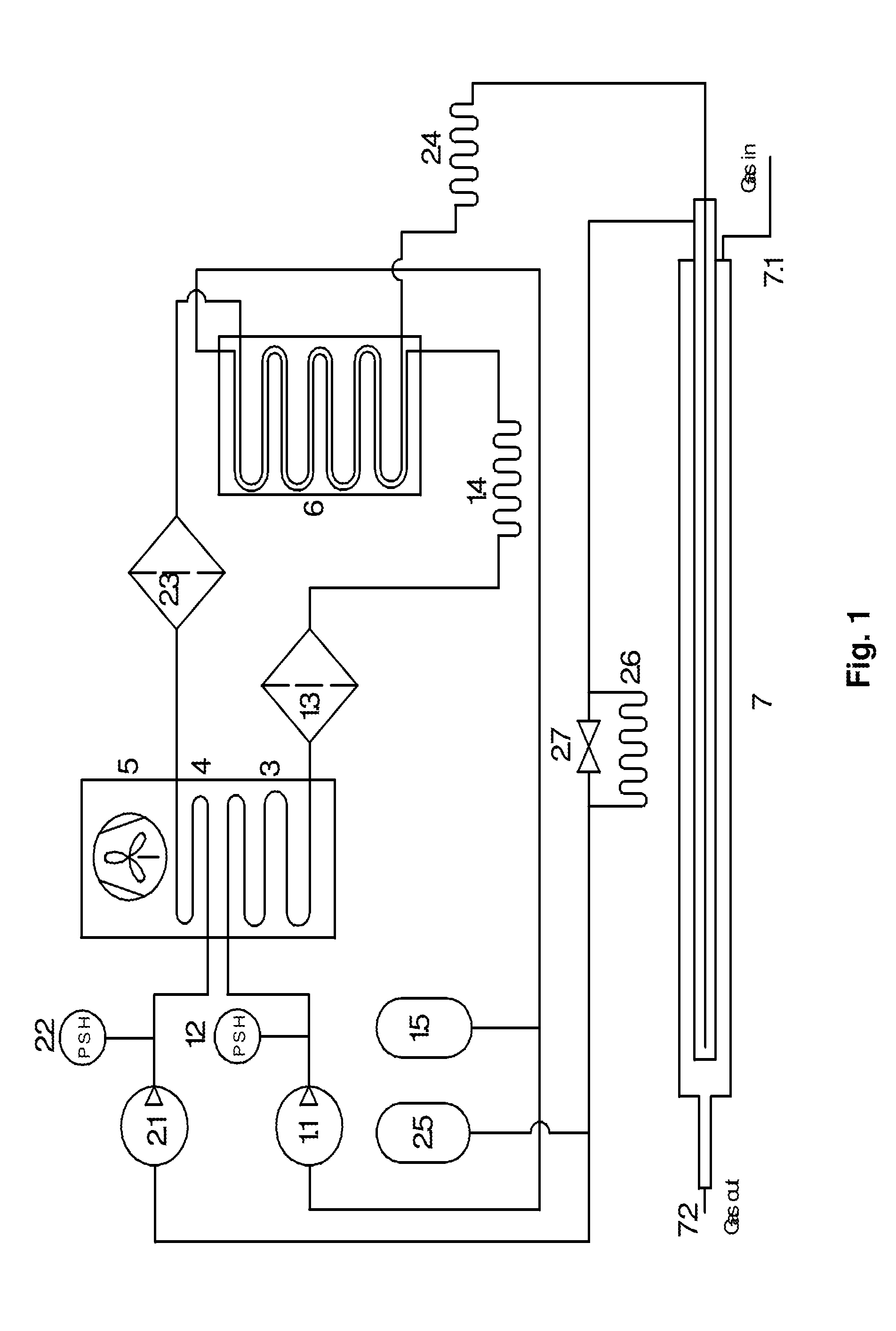
[0022]The cooling device shown by way of example in FIG. 1 includes a first cascade cooling stage with compressor 1.1, safety pressure switch 1.2, filter 1.3, relief throttle 1.4, and pressure compensating vessel 1.5 as well as a second cascade cooling stage with compressor 2.1, safety pressure switch 2.2, filter 2.3, relief throttle 2.4, and pressure compensating vessel 2.5.

[0023]A combined air heat exchanger with fan 5 is e.g. used as liquefier 3 for the first cascade cooling stage and as desuperheater 4 for the second cascade cooling stage.

[0024]A heat exchanger 6 is used as evaporator for the first cascade cooling stage and as liquefier for the second cascade cooling stage.

[0025]An evaporator (heat exchanger) 7, illustrated by way of example as transfer line of the cooling gas, is used as evaporator for the second cascade cooling stage to provide the desired cooling power in that the gas to be cooled is guided from the inlet 7.1 to the outlet 7.2.

[0026]In accordance with the inv...


PUM


Abstract

A cooling device for cooling a test sample has at least two cascade cooling stages, each with at least one coolant line, one compressor (1.1, 2.1), one relief throttle (1.4, 2.4), one evaporator (6, 7) and one liquefier (3, 6). The cooling device has an additional relief throttle disposed between the evaporator (7) of the last cascade cooling stage and the compressor (2.1) of the last cascade cooling stage. This represents a simple possibility of adjusting the cooling temperature, thereby avoiding the use of valves that can be adjusted at low temperatures, since these are complex and expensive.

Description

[0001]This application claims Paris Convention priority of DE 10 2011 006 165.7 filed Mar. 25, 2011 the complete disclosure of which is hereby incorporated by reference.BACKGROUND OF THE INVENTION[0002]The invention concerns a cooling device for cooling a test sample, comprising at least two cascade cooling stages, each comprising at least one coolant line, one compressor, one relief throttle, one evaporator and one liquefier.[0003]Devices having such properties are e.g. the device NMR90 of the company Millrock Technology, Kingston, N.Y., USA, the device ULSP90 of the company ULSP by, Ede, NL and the device FTS XR Air Jet of the company RototecSpintec GmbH, Biebesheim, Germany.[0004]Various analysis methods require cooling of the samples to be analyzed. In specific cases, such as nuclear magnetic resonance spectroscopy or X-ray crystallography, this is often achieved by introducing the sample into a cold gas flow (cooling gas), advantageously nitrogen or helium.[0005]This cold gas f...

Claims


Application Information

Patent Timeline
Patent Type & Authority Applications(United States)
IPC IPC(8): F25B7/00F25D29/00
CPCF25B7/00F25B41/30F25B41/22
Inventor MAYER, MARKUSSESTITO, FRANCO
Owner BRUKER BIOSPIN
Why Eureka
Try Eureka