Static electricity-visualizing material, static electricity-visualizing film, static electricity distribution-visualizing device, and static electricity distribution-visualizing method

Pending Publication Date: 2020-04-16
NAT INST OF ADVANCED IND SCI & TECH
View PDF5 Cites 1 Cited by
  • Summary
  • Abstract
  • Description
  • Claims
  • Application Information

AI Technical Summary

Benefits of technology

[0024]The object of the present invention is to provide a static electricity-visualizing material, a static electricity-visualizing film, a static electricity distribution-visualizing device, and a static electricity distribution-visualizing method, which makes it possible to intuitively understand a static electricity distribution by causing a charged region to emit light to visualize the charged region so that the charged region can be seen even with naked eyes.
[0025]The inventor of the present invention has continued research on static electricity, and for the first time in the world, the inventor has found a characteristic that the following fluorescent substance, lu

Problems solved by technology

However, the aforementioned electrostatic charging-measuring method (Patent Document 1) needs to locally vibrate the measurement object and thus cannot be applied to a measurement object which cannot be locally vibrated, which is a problem.
Also, for this method, the generated electromagnetic wave must be measured and visualized by a computer or the like, and th

Method used


Image

  • Static electricity-visualizing material, static electricity-visualizing film, static electricity distribution-visualizing device, and static electricity distribution-visualizing method
  • Static electricity-visualizing material, static electricity-visualizing film, static electricity distribution-visualizing device, and static electricity distribution-visualizing method
  • Static electricity-visualizing material, static electricity-visualizing film, static electricity distribution-visualizing device, and static electricity distribution-visualizing method

Examples


embodiment 1

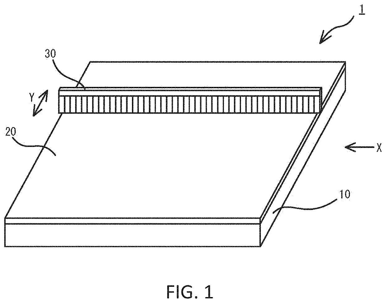
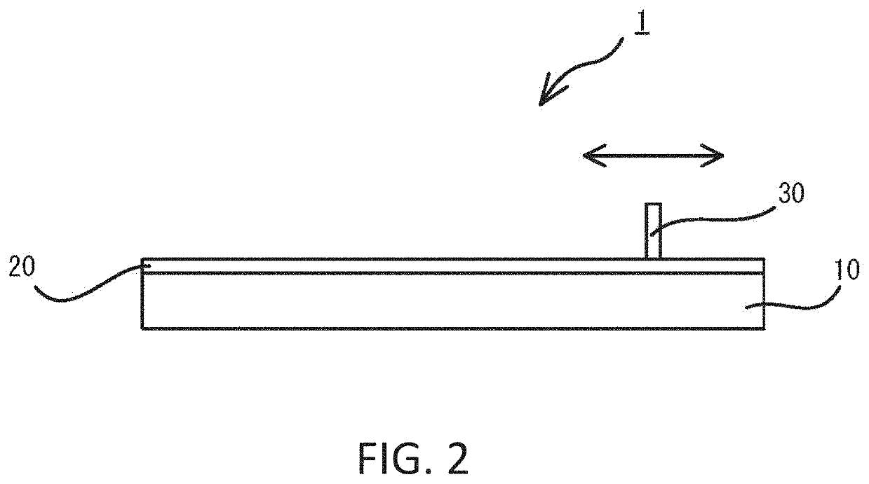
[0119]FIG. 1 illustrates a schematic perspective view of a static electricity-visualizing device according to Embodiment 1, and FIG. 2 illustrates a schematic side view of the static electricity-visualizing device according to Embodiment 1 viewed from X-direction in FIG. 1. As illustrated in these figures, in a static electricity-visualizing device 1 according to Embodiment 1, a static electricity-visualizing film 20 is formed throughout a surface of a rectangular flat measurement object 10, the static electricity-visualizing film 20 containing, as a static electricity-visualizing material, at least one of an fluorescent substance, a luminescent substance, an electroluminescent substance, a breaking luminescent substance, a photochromic substance, an afterglow substance, a photostimulated luminescent substance, and a mechanoluminescent substance.

[0120]In addition, on the static electricity-visualizing film 20, a destaticizing brush 30 having a width equal to or larger than breadths ...

example 1

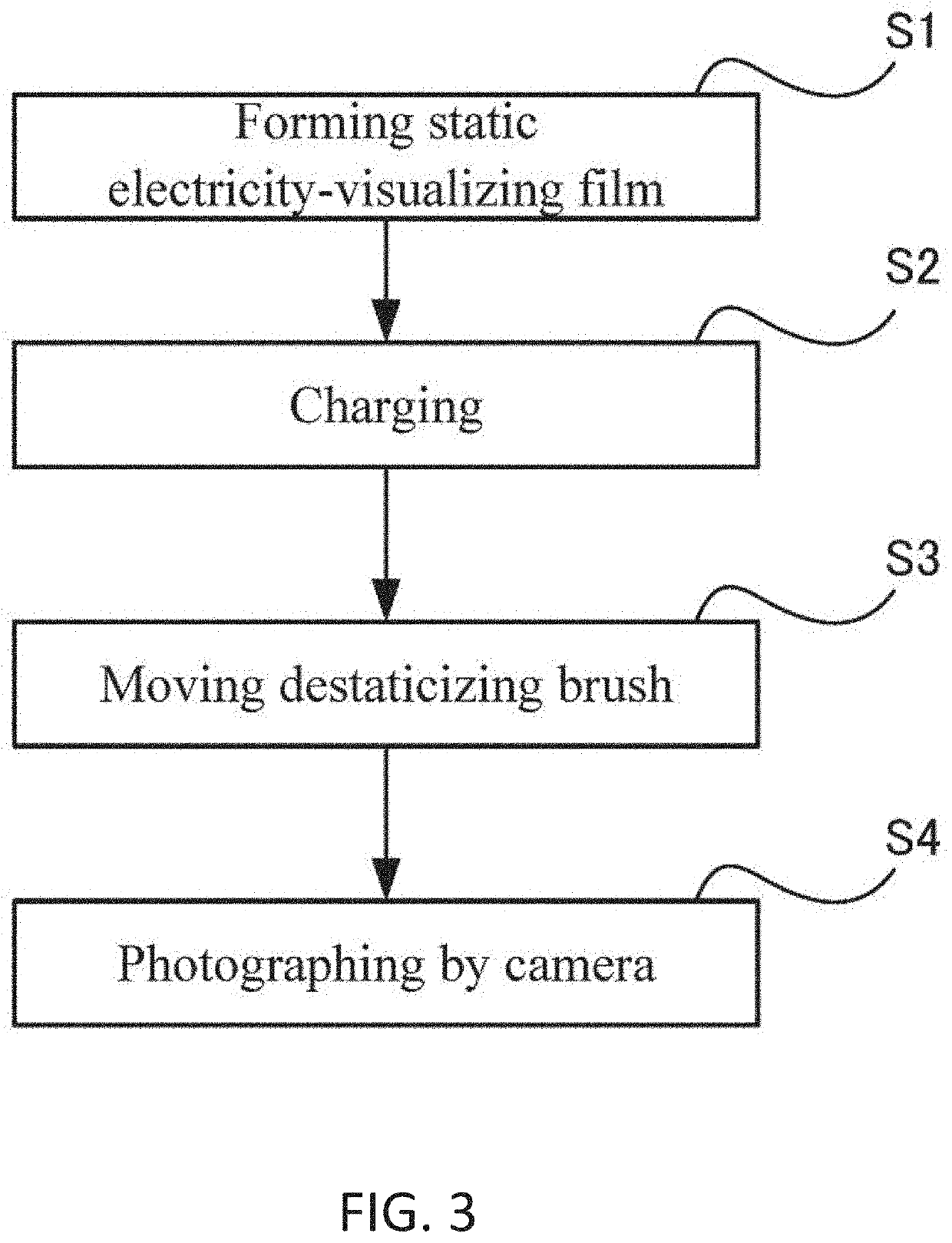
[0133]A mixture of SrAl2O4:Eu2+ and a photocurable acrylic resin (manufactured by MICROJET Corporation) (SrAl2O4:Eu2+ weight ratio: 70%) was applied on an aluminum foil and cured as a static electricity-visualizing film. Shown are: a result obtained by charging the static electricity-visualizing film for 9 seconds by corona discharge, and then sweeping a surface of the static electricity-visualizing film with a destaticizing brush; and a result obtained by measuring the static electricity-visualizing film charged under the same condition as above by the static electricity distribution-measuring method disclosed in Japanese Patent Application No. 2016-085485.

[0134]FIG. 4 is a photograph showing a result of sweeping the surface of the static electricity-visualizing film with the destaticizing brush. FIG. 5 is a diagram illustrating a static electricity distribution measured by the electrostatic charging-measuring method disclosed in Japanese Patent Application No. 2016-085485.

[0135]As...

embodiment 2

[0136]Although physical stimulation for stimulating the static electricity-visualizing film is used as the visualization means in Embodiment 1, the present invention is not limited thereto. For example, the static electricity-visualizing film may be stimulated using a magnet as the visualization means.

[0137]FIG. 6 is a schematic side view of a static electricity-visualizing device 1A according to Embodiment 2. As illustrated in FIG. 6, the static electricity-visualizing device 1A according to Embodiment 2 has the same configuration as that of the static electricity-visualizing device according to Embodiment 1 except that, instead of the destaticizing brush, a magnet 30A which is a visualization unit having square side faces is disposed above the measurement object 10.

[0138]The magnet 30A has a width equal to or larger than breadths of the measurement object 10 and the static electricity-visualizing film 20, arranged so that its position relative to the static electricity-visualizing...


PUM

PropertyMeasurementUnit
Temperatureaaaaaaaaaa
Magnetic fieldaaaaaaaaaa
Weight ratioaaaaaaaaaa

Abstract

[Problem]
The object of the present invention is to provide a static electricity distribution-visualizing material, a static electricity-visualizing film, a static electricity distribution-visualizing device, and a static electricity distribution-visualizing method, which can visualize a charged state to be seen with naked eyes so as to intuitively understand a static electricity distribution.
[Solution]
A static electricity distribution-visualizing material is manufactured so as to contain at least one of a fluorescent substance, a luminescent substance, an electroluminescent substance, a fractoluminescent substance, a photochromic substance, an afterglow substance, a photostimulated luminescent substance and a mechanoluminescent substance.

Description

TECHNICAL FIELD[0001]The present invention relates to a static electricity-visualizing material, a static electricity-visualizing film, a static electricity distribution-visualizing device, and a static electricity distribution-visualizing method, which make it possible to visualize a charged state of static electricity charged on various parts and devices.BACKGROUND ART[0002]In Japan, various manufacturing sectors support foundation of industries such as semiconductor manufacture, electronic / electric equipment manufacture, precision machine manufacture, transportation machine manufacture, chemical manufacture, fiber manufacture, ceramic manufacture, pharmaceutical manufacture and food manufacture. In factories responsible for actual manufactures in such manufacturing sectors, products are assembled in an automatic process or an artificial process with many parts flowing through a production line.[0003]Herein, there are problems that defects or failures in parts constituting a produ...

Claims


Application Information

Patent Timeline
IPC IPC(8): G01R29/24G01R29/14C09K11/77C09K11/02
CPCC09K11/7734G01R29/14C09K11/02G01R29/24C09D7/40C09D7/61C09D201/00C09K11/00C09K11/64G01R29/12
Inventor TERASAKI, NAOKIKUNAGA, KAZUYA
Owner NAT INST OF ADVANCED IND SCI & TECH
Why Eureka
Try Eureka