Antiseptic cap

a technology of antiseptic caps and syringes, which is applied in the field of antiseptic caps, can solve the problems of catheters, catheters, and catheters being occluded by thrombosis, and achieve the effect of preventing relative rotational movemen

Active Publication Date: 2020-04-23
EXCELSIOR MEDICAL
View PDF0 Cites 16 Cited by
  • Summary
  • Abstract
  • Description
  • Claims
  • Application Information

AI Technical Summary

Benefits of technology

[0011]The present invention relates to an antiseptic cap and syringe combination. The combination includes a syringe barrel having an access point connection, and a tip cap having a proximal chamber and a distal chamber. The proximal chamber releasably receives and engages the access point connecti

Problems solved by technology

Although a preferred mode of vascular access for a hemodialysis patient involves using an arteriovenous (AV) fistula of either the upper or lower extremities or an arteriovenous “bridge” graft (typically utilizing PTFE), use of these access devices is not always possible or desirable.
When either of these modes of vascular access is not available, for example

Method used


Image

  • Antiseptic cap
  • Antiseptic cap
  • Antiseptic cap

Examples


Embodiment Construction

[0132]While this invention is susceptible of embodiment in many different forms, there is shown in the drawings, and will be described herein in detail, specific embodiments thereof with the understanding that the present disclosure is to be considered as an exemplification of the principles of the invention and is not intended to limit the invention to the specific embodiments illustrated.

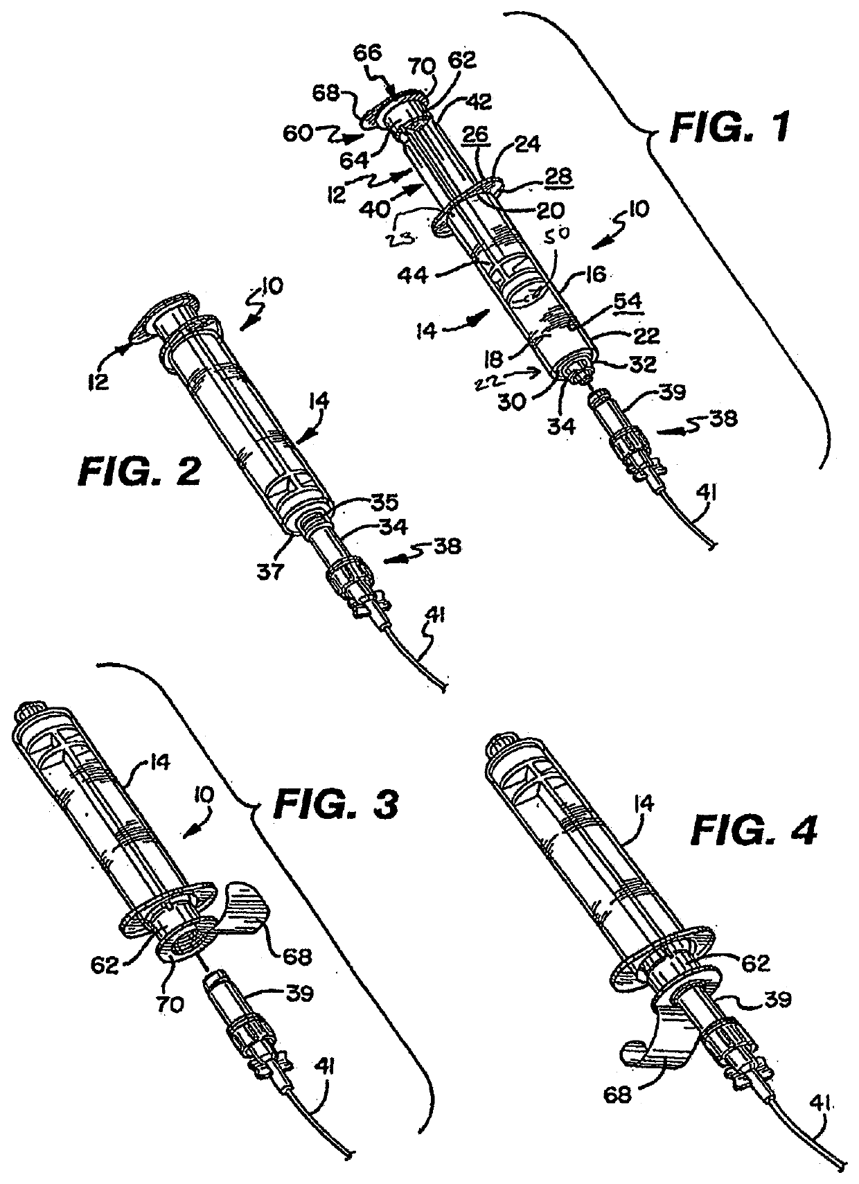
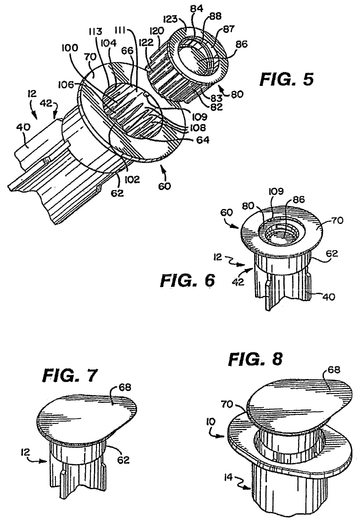
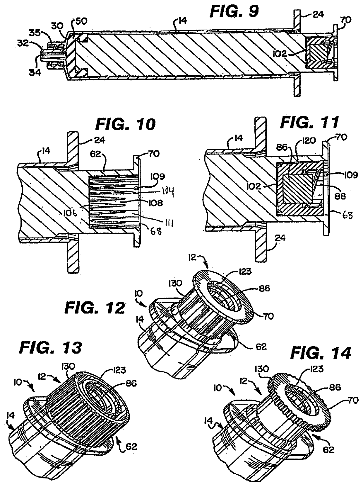
[0133]FIGS. 1 and 2 show an antiseptic cap equipped plunger and syringe barrel assembly 10 having an antiseptic cap equipped plunger (or piston) assembly 12 and a syringe barrel 14. The barrel 14 has a side wall 16 defining a chamber 18 and the barrel has a proximal end 20 and a distal end 22. The proximal end 20 has an opening 22 to the chamber 18 and a flange 24 extending radially outwardly from the wall 16. The flange 24 has upper and lower surfaces 26, 28 and provides gripping surfaces for a user of the assembly 10. The distal end 22 of the barrel 14 has an end wall 30 and an elongate tip 32 e...


PUM


Abstract

A syringe assembly including: (1) a syringe barrel defining a chamber; (2) a plunger mounted in the chamber and moveable with respect to the barrel; and (3) a cap holder assembly containing a cap and an absorbent material removably attached to the syringe.

Description

CROSS-REFERENCE TO RELATED APPLICATIONS[0001]This application is a continuation application of U.S. patent application Ser. No. 15 / 637,998, filed on Jun. 29, 2017, which is a continuation application of U.S. patent application Ser. No. 14 / 799,022, filed on Jul. 14, 2015, now U.S. Pat. No. 9,707,350, which is a continuation application of U.S. patent application Ser. No. 13 / 547,650, filed on Jul. 12, 2012, now U.S. Pat. No. 9,259,535, which is a continuation-in-part of U.S. patent application Ser. No. 13 / 288,529, filed on Nov. 3, 2011, now U.S. Pat. No. 9,700,710, which is a continuation-in-part of U.S. application Ser. No. 12 / 214,526, filed on Jun. 19, 2008, now U.S. Pat. No. 9,707,348, which is a continuation-in-part of U.S. application Ser. No. 11 / 821,190 filed on Jun. 22, 2007, now U.S. Pat. No. 8,167,847, which claims the benefit of U.S. Provisional Application Ser. No. 60 / 815,806 filed on Jun. 22, 2006, and U.S. patent application Ser. No. 13 / 288,529 is a continuation-in-part o...

Claims


Application Information

Patent Timeline
IPC IPC(8): A61M5/315A61M39/20A61M39/16A61M39/02A61M5/31A61M25/04
CPCA61M2005/31506A61M39/162A61M5/347A61M2005/3104A61M2025/0019A61M5/3137A61M39/16A61M5/002A61M5/31513A61M2039/1033A61M39/02A61M25/04A61M5/31511A61M5/31A61M5/001A61M39/20A61M5/3135A61M2205/0205
Inventor ANDERSON, WILLIAMWILSON, MARKHENNIGER, GARYCOLQUITT, LARRYGARDNER, CHRISTOPHER E.WALAWALKAR, CHIRAG SANJAY
Owner EXCELSIOR MEDICAL
Why Eureka
Try Eureka