Integrated ir receiver in side-lit panels

a technology of side-lit panels and receivers, which is applied in the direction of instruments, lighting and heating apparatus, semiconductor devices for light sources, etc., can solve the problems of introducing extra materials and assembling costs, affecting the look and feel of the device, and affecting the light distribution. to achieve the effect of facilitating the direction of the axis

Active Publication Date: 2020-04-23
SIGNIFY HLDG BV
View PDF5 Cites 4 Cited by
  • Summary
  • Abstract
  • Description
  • Claims
  • Application Information

AI Technical Summary

Benefits of technology

[0008]The invention especially provides a solution for invisible integration of an infrared sensor in side-lit panels. The lighting device does not require a lens commonly used for the IR function. The lighting device does not need an IR-eye used in, and visible in or on, most products that are equipped with IR sensor(s) nowadays. The lighting device may be cheaper than prior art solutions by omitting (additional) components normally used for the application of the IR sensor. Further, the invention enables smoother product design. Essentially, the solution is surprisingly found by using the light guide plate for an additional function of guiding the IR signal.
[0030]The rim may shield the light sources. Especially, the light sources are not visible from a location downstream of the light guide plate. They are especially not in “the line of sight”. The rim may allow light source light to be coupled in the light guide plate. In the rim, the light source light is especially directed to the light guide plate. Especially, the rim prevents light source light from escaping in another direction (from the rim). The rim may further comprise an esthetic function. In embodiments, the rim is arranged surrounding the edge of the light guide plate, especially substantially around the entire edge of the light guide plate. The rim especially does not comprise holes, such as holes for entering of IR radiation into the lighting device (known in the art). The rim may contact the first face and especially also the second face of the light guide plate.
[0041]Due to the arrangement of the IR sensor, the additional space required for the sensor is minimal or even negligible. Hence, the rim does not claim more space than necessary for the light sources, and e.g. the control device. This allows a very economic and smooth design of the lighting device. In embodiments, a distance between the light sources, and especially (also) the IR sensor, and the edge of the light guide plate is in the mm-range. In further embodiments the distance is less than 1 mm, such as less than 0.1 mm, or even less. Especially, a distance between the IR sensor and the edge of the light guide plate is a non-zero distance. The light sources may in embodiments not contact the edge of the light guide plate. In further embodiments the light sources may contact the edge of the light guide plate. The IR sensor may in embodiments (also) not contact the edge of the light guide plate.

Problems solved by technology

These solutions may be functional but may have a negative impact on the look and feel of the device.
Further, such sensors may have impact on the light distribution, as such sensors may e.g. block part of a reflector.
Prior art solutions may further comprise additional elements, introducing extra costs for material as well as assembling.

Method used


Image

  • Integrated ir receiver in side-lit panels
  • Integrated ir receiver in side-lit panels

Examples


Embodiment Construction

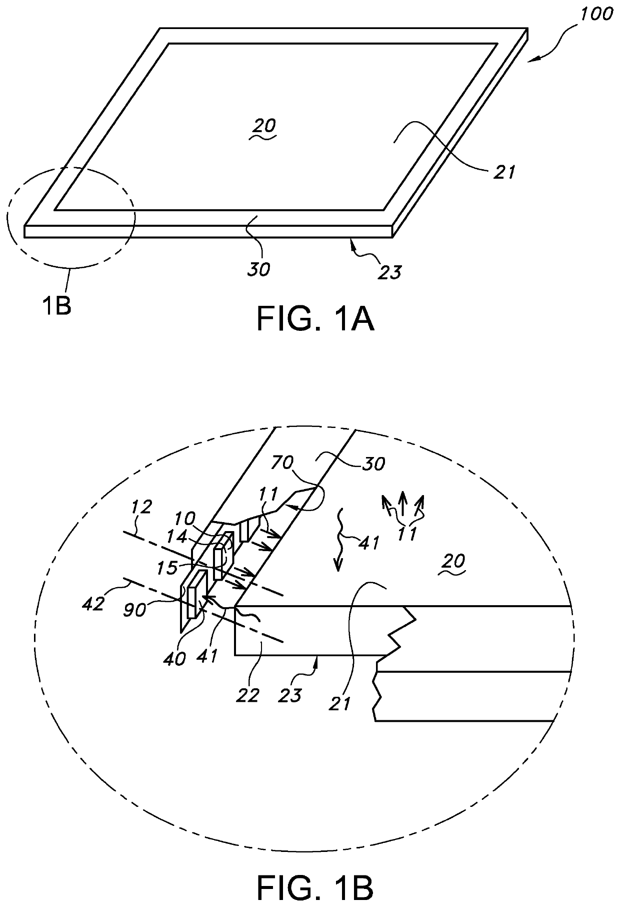
[0060]In FIG. 1a and FIG. 1b schematically an embodiment of the lighting device 100 is depicted. The lighting device comprises a light guide plate 20 and a rim 30 surrounding the circumferential edge 22 of the light guide plate 20. The light guide plate 20 comprises a first face 21 and a second face 23. The lighting device 100, especially the light guide plate 20 of the invention may comprise any arbitrarily shape. In the given embodiment the light guide plate 20 comprises a rectangular shape, especially a square shape.

[0061]FIG. 1b shows a part of the embodiment of FIG. 1a in more detail. In the figure a part (two) of the plurality of light sources 10 is visible as well as an IR sensor 40. The figure further shows that the rim 30 comprises the light sources 10 and the IR sensor 40. The light sources 10 are configured to provide light source light 11. The light guide plate 20 comprises a circumferential edge 22. In the figure the light sources 10 provide light source light 11 in a d...


PUM

PropertyMeasurementUnit
distanceaaaaaaaaaa
distanceaaaaaaaaaa
mutual angleaaaaaaaaaa

Abstract

The invention provides a lighting device (100) comprising a plurality of light sources (10), a light guide plate (20), a rim (30), and an IR sensor (40), wherein: (i) the light sources (10) are configured to provide light source light (11), and wherein the light sources (10) are configured in an edge-lighting configuration with the light guide plate (20); (ii) the light guide plate (20) comprises a circumferential edge (22) of which at least part is 5 configured as light incoupling face for the light source light (11), and a first face (21) of which at least part is configured as light outcoupling face; (iii) the rim (30) comprises the plurality of light sources (10) and the IR sensor (40); and (iv) the IR sensor (40) is configured to sense IR radiation (41) via the light guide plate (20).

Description

FIELD OF THE INVENTION[0001]The invention relates to a lighting device comprising a light guide plate and a rim comprising a plurality of light sources and an IR sensor, wherein the light guide plate guides the light source light as well as the IR radiation. The invention further relates to a lighting system comprising such lighting device.BACKGROUND OF THE INVENTION[0002]The use of IR (infra-red) sensors is known in the art. US20160004008, for instance, describes in an embodiment a switch and socket housing of a guiding light platform. The switch and socket housing may include a switch bore for holding therein the on / off switch, and a socket bore for holding therein the recharge socket. The guiding light platform may be controlled by an infrared remote control. The infrared remote control can be provided with a plurality of buttons. The buttons can be used to switch on, switch off, change color, adjust brightness and control color-changing modes of the LEDs. The color-changing mode...

Claims


Application Information

Patent Timeline
Patent Type & Authority Applications(United States)
IPC IPC(8): F21V23/04F21V8/00
CPCG02B6/0068G02B6/0055F21V23/0471F21Y2115/10G02B6/0011G02B6/0051G02B6/0073G02B6/0081G02B6/4298
Inventor VAN RIJSWIJK, NICOLAAS ANTONIEDERGEM-DE BEST, ANNA WILHELMINA MARIAWEGH, RENE THEODORUS
Owner SIGNIFY HLDG BV
Why Eureka
Try Eureka